This thread has been locked.

If you have a related question, please click the "Ask a related question" button in the top right corner. The newly created question will be automatically linked to this question.

LM5116: DEMB pin functionality

Part Number: LM5116

Hi!

If I am reading the datasheet (section 6.4.1) and related questions correctly, the DEMB resistor sets the load current at which the low-side fet switches from diode to synchronous mode?

"When RDEMB=0, the LM5116 will always run in diode emulation."

and 

"Full synchronous operation is obtained if the DEMB pin is always biased to a higher potential than the SW pin when LO is high. RDEMB = 10 kΩ will bias the DEMB pin to 0.45V minimum, which is adequate for most applications"

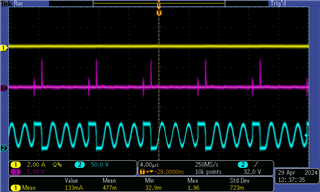
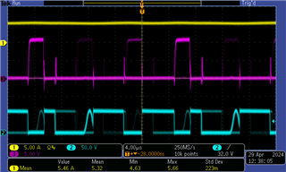
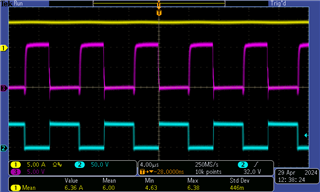
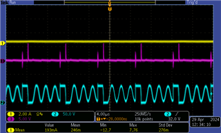
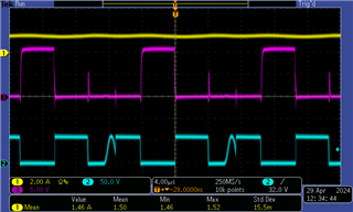
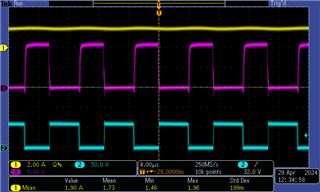
However, I haven't been able to force the low-side fet to stay as a diode or synchronous mode no matter what resistor I populate for RDEMB. The traces below show load current (yellow, with "value" measurement), low-side fet gate voltage (magenta) and switching node voltage (cyan). According to the datasheet, the plots should be the same for the resistor values I used here, but this is not the case. 

One minor notice is that it takes a much higher current for the 0ohm circuit to enter synch mode and vice versa at least, so I'm assuming something is working.

low current (diode mode) in between (sometimes diode or synch mode) high current (synch mode)
0 ohm RDEMB (should theoretically only ever be in diode mode)

open circuit RDEMB (should theoretically always be in synchronous mode)

  • Hello Robert 

    Would you please re-test with 10kOhm DEMB resistor ? DEMB pin is sensitive. The DEMB resistor should be cdirectly onnected to the ground connection of the current sense resistor. 

    It looks like the 0-ohm RDEMB operation is correct. At heavy load when the valley current is greater than zero, the converter works in CCM (Continuous-conduction-mode). 

    -EL

  • I tested with a 10k resistor and got identical results, just at different load currents. I'm not sure I understand your comment- the "heavy load" shown in my photos is much lower than the set current limit. I am able to continue to increase the load current significantly past what is shown here, this is just at a load current where the effects start to be visible.  

    As far as I understand, the datasheet says that with a 0ohm RDEMB, the low-side fet should never be turned on, otherwise by definition it no longer is in diode mode. But the waveforms show that the low-side fet is conducting which should not be happening? 

  • Hello Robert 

    As far as I understand, the datasheet says that with a 0ohm RDEMB, the low-side fet should never be turned on ==> This is a misunderstanding. In the diode emulation mode, the low-side MOSFET turns on when the inductor current is positive and the device tries to turn it off before the inductor current goes negative. 

    -EL