


Hello,
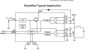
we have two inputs EN and PWM for switching. When we applied EN =5V and PWM signal (pulse width = 10us duty cycle = %1 duty cycle), switching works correctly. But If EN = 0V, we measure 4.5V at HS node. İs this normal?
Best Regards
Ümit
Hello,
we have two inputs EN and PWM for switching. When we applied EN =5V and PWM signal (pulse width = 10us duty cycle = %1 duty cycle), switching works correctly. But If EN = 0V, we measure 4.5V at HS node. İs this normal?
Best Regards
Ümit
