Hello,
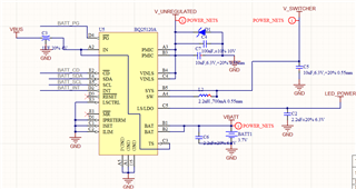
We have the BQ25120A on 10 prototype PCBs. 8 of them work as expected, but 2 of them have much higher VSYS ripple. This is all done at VSYS 1.75V and 100uA-300uA current (changes dynamically with device function but the problem persists regardless of current) with 2.2uH/10uF output filter.
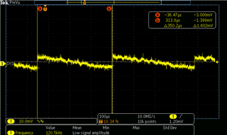
The 8 good units measure something like this:
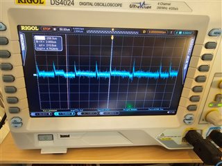
The bad units look like this:
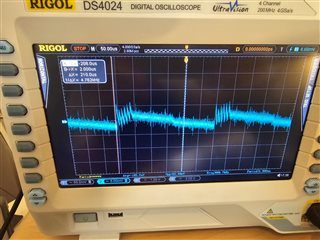
The discharge slope varies a bit between images due to the variation in current but the problem is always the same. The "good" switching sequence is what I would expect, but the "bad" sequence seems to enable SW several times in bursts and drive VSYS much higher and then wait for larger droop before switching multiple times again.
I have tried transplanting "good" inductors and caps to the bad boards and changing pretty much all components around the BQ but it makes no difference. I have replacement BQ parts on order so I can change those as well. The "good" waveform is what I would expect from VSYS.
Questions:
1. Is this difference in switching behavior expected?
2. What are the 2 different switching modes shown in good and bad? I don't see the burst of "bad" SW enables in the spec sheet anywhere.
3. What causes 2 BQ parts to switch so differently under very similar conditions?
4. How can I prevent this difference in switching and lower the output ripple to always be like "good"
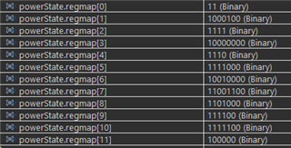
5. Are there hidden registers to modify this behavior so that all BQ units will behave like "good"?
Cheers