This thread has been locked.

If you have a related question, please click the "Ask a related question" button in the top right corner. The newly created question will be automatically linked to this question.

LM2651: LM2651 sleep mode threshold issue

Part Number: LM2651

Hello,

We have a regulator designed with "LM2651MTC-3.3/NOPB" part number and our characterization shows that the sleep mode current for this design is 250mA instead of 100mA.

Input:5V, output: 3.3V

Output capacitance: 150uF

Inductance: 39uH

This sleep mode load value of 250mA doesn't match the datasheet typical value of 100mA and is problematic for us. 

To understand what the problem might be, we purchased the evaluation board for this regulator (LM2651-3.3EVAL/NOPB), and tested it. Even for the evaluation board, the sleep mode limit was 200mA and not 100mA.

On the evaluation board, we used a 5V input, the output was at almost 3.3V and it was regulating at 300kHz with <10mVpp of ripple for loads above 200mA, not 100mA.

The image below shows the output ripple of about 60mVpp at 8KHz, at 110mA of load for the evaluation board:

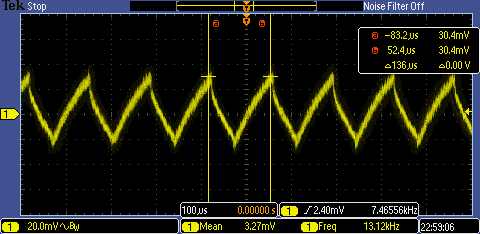
The next image shows the output ripple of about 60mVpp at 2.8KHz, at 180mA of load for the evaluation board:

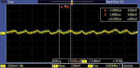
The next image shows the output ripple at 200mA of load, with 300kHz of ripple frequency at about 11mVpp:

Could you please explain where the discrepancy between the 100mA of the datasheet and the 200mA of the evaluation board, (or the 250mA of our design) is coming from and how to lower down the limit to the datasheet typical value of 100mA?

Thanks,

Parisa

  • Hi Parisa,

    Since it is currently a Chinese holiday (May 1st to May 5th), my colleague Emma will reply to you after the holiday. Thanks for your patience.

    Aurora

  • Hi Parisa,

    Thank you for your patience. As this is an old device and we don't have the EVM in hand right now. I have applied a new one but it takes time to arrive. 

    Have you tried the other way around by deceasing the current from large to small and see what is the threshold? Also, as 100mA is the typical value only, the actual threshold current can vary. 

    And to decrease the threshold, from Datasheet Page 15 Figure 13, using a smaller inductor may help. 


    Regards,

    Emma Wu

  • Hello,

    Thank you for your reply. Yes, I have tried to find the threshold both ways, higher to lower and lower to higher values, with small steps, and both ways it is 200mA.

    Of course, I understand there is a tolerance, but 100% tolerance doesn't sound right. I tested this on two of our own designs and the evaluation board and all of them have 200mA+ thresholds. I would say this is not normal. 

    Also, figure 13 is for the ADJ version, and doesn't really show a 5V output current threshold anyway, but I see your point and will relay that to the design team.

    Looking forward to your findings,

    Thanks!

    Parisa

  • Hi Parisa,

    Yes although Fig13 is for the ADJ version but I think the internal architecture should be the same. (The design resource is not available for confirmation as this is old device). We can try smaller inductor like 22uH to see if there is any change on the results. You can also take the BOM of our EVM as a reference. 

    Regards,

    Emma 

  • Hello,

    Did you receive the board? And do you have any updates for me? Thank you!

  • Hi Parisa,

    My colleague Emma will give you response during these days. Thanks for your understanding!

    BRs

    Lucia

  • Hi Parisa,

    Sorry for keeping you wait. I just checked internally for the EVM status and found it's not available anymore in our free sample stock as it is too old. Have you tried smaller inductor like 22uH and see any change on the test results?

    Regards,

    Emma