Because of the holidays, TI E2E™ design support forum responses will be delayed from Dec. 25 through Jan. 2. Thank you for your patience.

This thread has been locked.

If you have a related question, please click the "Ask a related question" button in the top right corner. The newly created question will be automatically linked to this question.

LMR51430: How does the PFM version works in light load?

Part Number: LMR51430

Hi team,

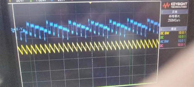
How does the PFM version works in light load? In customer system, they use two pieces LMR51430. One Vin=24V, Vout=5V,Iout=200mA. The other one is Vin=5V Vout=3.3V Iout=20mA.

The capture shows the blue channel is 24V-->5V's 5V output, the yellow channel is 3.3V output from the second channel. Why the waveform is like that in blue channel?
  • Hello,

    Please let me know what the waveform in both blue channel and yellow channel are.

    1. Is it SW or inductor current? 
    2. How is the waveform being measured? Are you hovering the probe around any noisy circuit or inductor which can capacitively couple SW to probe?
    3. Do you have a schematic I can review for both circuits?

    Information about PFM configuration in light load are detailed in the datasheet below:

    Regards,

    Jimmy