Because of the Thanksgiving holiday in the U.S., TI E2E™ design support forum responses may be delayed from November 25 through December 2. Thank you for your patience.

This thread has been locked.

If you have a related question, please click the "Ask a related question" button in the top right corner. The newly created question will be automatically linked to this question.

TPS61033: GSM/LTE module power supply from LiSOCl2 3.6V battery

Part Number: TPS61033
Other Parts Discussed in Thread: TPS61230A, TPS61230, , TPS61022, TPS61253A

The IOT device is powered by a 3.6V 14.5Ah LiSOCl2 Non-rechargeable battery.
The device contains 2 powerful consumers: a GSM/LTE module and a UHF RF module.
GSM module - 3.8V / 2.0A, UHF RF 5.0V / 2.2A.
The current revision of the board uses the following converters:
1. GSM power supply - FAN48623.
2. UHF RF Power - TPS61230A
FAN48623 did not suit us because... it is BGA, TPS61230A stopped working if the input voltage dropped below 2.5V.
In the next revision I would like to use a converter from the TPSxxxx line.
1. It is highly desirable to use the same boost DC-DC IC for GSM and UHF power supply.
2. It is advisable not to use BGA.
3. When working with GSM+UHF, the battery power may not be enough and the voltage may drop to 2.3-2.4V. Now in this case the TPS61230 stops delivering 5.0V / 2.2A. 

For the test, a board with TPS61033 was made. I assumed that it might not be suitable for getting 5.0V / 2.2A, but I was sure of getting 3.8V / 2.0A... but it turned out wrong :(
For the second day now I have been unable to start GSM: at the moment of registration in the GSM network, I see a current jump of 1.5A and the MCU reboots. The reason for the reboot is a voltage drop below the minimum permissible value. The device is powered by a 3.6V power supply with a current limit of 4A. Visually, this looks like a short circuit at the Vin input of the TPS61033. Moreover, if you specially short-circuit Vout, then the current is limited normally and with a short circuit of Vout TPS61033, the rest of the circuit continues to work normally.
If the input voltage of the device is increased so that the TPS61033 switches to Pass-through mode, then everything works fine.
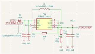


During the debugging process, I increased the output capacitance to 4x22uF, removed R18, saw that the GND path was not very good and duplicated it with a short wire, removed the D5 diode (with the help of it I wanted to isolate the GSM power supply from the UHF RF power... so that short-term power failures from UHF operation would not led to a reboot of LTE (LTE can sleep and consume <1ma)).
This didn't help...

Tell me what I'm doing wrong with the TPS61033 or tell me the correct choice of other devices.

  • Hello Oleksandr,

    The expert for this device is out of the office this week, so please expect a detailed answer beginning of next week.

    Could you please in the meantime send measurements of the input and output voltage when the issue occurs? I wonder if the requested current from the battery causes a voltage drop at the input of the device and disables the output.

    Best regards,
    Brigitte


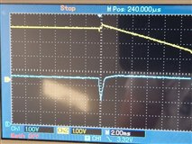
  • CH1 Vin
    CH2 Vout

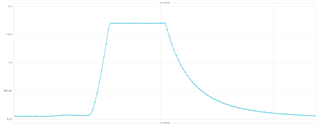
    Current consumption Vin at this moment:


    Did some more research.
    I replaced the power source with a powerful battery... and saw the device working normally :)
    Previously, a digitally controlled power supply was used. Apparently these short current pulses somehow influenced its control circuit.
    But I still don’t understand why the same power supply worked perfectly with FAN48623 and does not work at all with TPS61033. 
    With the TPS61033, operation stops at the first current pulse.


    p.s. 1.7A is limit of ampermeter. Apparently there is a very large current pulse there. Why?


    This is what the Vin current looks like when there is a short circuit at the TPS61033 output


    This is what the start of the second 3.6V - 5.0V converter looks like. We see the switching on and current surge, while the input voltage drop to 2.4V and the system reboots.


  • Hello Oleksandr,

    Please check as well the EN signal when the device stops switching.

    Best regards,
    Brigitte

  • Everything is OK with the EN signal - it drops to zero due to the microcontroller rebooting.
    short circuit at the TPS61033 input -> input voltage drop below 2.2V -> microcontroller reboot -> signal drop En

  • Hello Oleksandr,

    So at the right of the drop on VIN, the EN signal is 0, right?

    Best regards,
    Brigitte

  • Hi Oleksandr,

    It seems that the first pulse appears when the TPS61033 starts up. It is a startup current of TPS61033.

    The current limit of FAN48623 in startup phase is smaller than TPS61033, so I think this is why it can work normally with FAN48623 + digitally controlled power supply.

    By the way, we have several recommendations about the schematic and layout.

    1.For the inductor and the output capacitor, we recommend to use 0.47uH and 4x22uF if the output current is higher than 1A

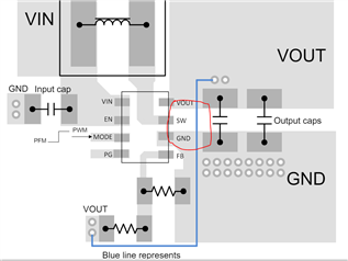
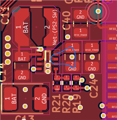
    2.For the layout, the output capacitor should be placed as close as to VOUT GND pad, the area of this red loop should be as small as possible.

    You can refer to the layout guidance below.

    Regards,

    Nathan

  • Thanks for the answer, but it’s not a matter of starts up or a digitally controlled power supply.
    The problem arises long after the start with sudden surges in current in the load.
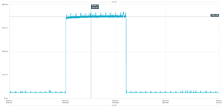
    Here you can clearly see the soft starts up, normal operation and current surges:


    The inductor was chosen with a nominal value of 1uH because this does not contradict the recommendations from the datasheet. 

    Now I don’t have the correct inductance 0.47uH at hand, but I tried adding 2 more 22uF capacitors - this also did not give a positive result.

    The output capacitor is positioned as correctly as possible:
    The board is 4-layer. Vias go to layers with a solid GND polygon 


    I also tried changing the auto PFM and forced PWM modes.


    Overall, is the TPS61033 suitable for my needs or would you recommend something else?
    I need to get 2 power supplies from a battery with an input voltage of 2.5 - 4.2V:
    1. 3.8V/2.0A for GSM power supply
    2. 5.0V/2.0-2.5A to power the RF transmitter.

    1. Both devices consume current in short bursts.
    2. Due to the rather high consumption, the resistance of the board, power wires, etc. is affected. It is advisable to maintain operation when the input voltage drops below 2.5V for a short time.

  • Hi Oleksandr,

    TPS61033 can support 3.8V/2A, but can't support 5.0V/2A-2.5A.

    TPS61022 can support 5V/2A-2.5A.

    Both of the device would consume ~330mA current from input when short occurs. It is the short protection behavior of these devices.

    Both of the device can work when input voltage drops below 2.5V for a short time, with EN=high.

    Unfortunately we don't have a device that would not consume large current in short, only TPS61253A would not but it is BGA package.

    Regards,

    Nathan

  • Thanks for the recommendations!
    Can you explain it as a description


    then it turns out that "can't support 5.0V/2A-2.5A"

  • Hi Oleksandr,

    5-A means the switching current, or inductor current.

    For Boost converter, the inductor current is equal to input current, not output current. This is different with Buck converter.

    So it means the input current can be as high as about ~5A. And the maximum output current can be calculated by VIN*IIN*eff / VOUT.

    For you application, VIN minimum is 2.3V, and the maximum output power is 5V*2.5A=12.5W, assume the efficiency = 0.9, the input current at this condition is about 12.5/2.3/0.9=6A, higher than 5A of TPS61033, so TPS61033 can't support this condition.

    Hope this answer could explain it.

    Regards,

    Nathan