This thread has been locked.

If you have a related question, please click the "Ask a related question" button in the top right corner. The newly created question will be automatically linked to this question.

TPS25961: eFuse not activating

Part Number: TPS25961

Hi there! I am facing some issues with this eFuse. Some context.

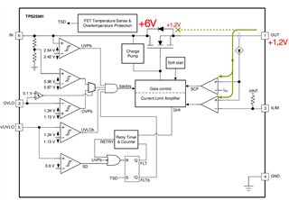
- I am using this eFuse to activate/deactivate a 6V rail in my PCB, so Vin=6V.

-The eFuse is limited to about 200mA using a 243K resistor attached to ILIM pin.

- Enable pin has a external pull-down (10K) and 100nF cap and it's connected directly to a GPIO of a MCU. (0-3,3V)

- OVLO pin has a external resistor divider 51K up and 10K down to +6V rail.

The point is:

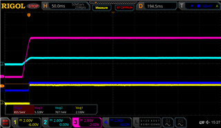
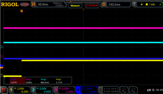
The eFuse is working fine, sometimes, but some others it's not activating the output. What I've seen is that there is some voltage at the output when the eFuse is not active, something like 1,2V, because of the circuit connected to the eFuse output (this is something I can't change, as it's an external device)

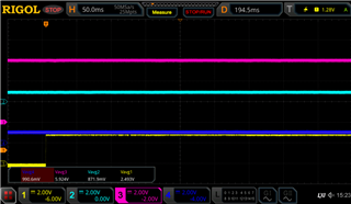
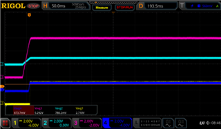
When the device works, I can see this waveform:

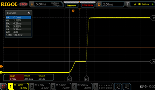
And when it does not work, the ouput directly is not activated and remains to ~1,2V. The first little step to 1,2V is when the system is energyzed, but eFuse still off, and then when eFuse is activated, the output reaches the 6V.

Any idea of what can be happening? I haven't seen anything relevant in the datasheet... any help is very welcome.

Thanks!!

  • Hi Alberto,

    In the waveform, can you probe EN, OVLO, IN, OUT all in same waveform for both successful startup and failed startup case. Please keep the time division of at least 20ms/div. (preferably 50ms/div). Please once check the soldering on the PCB. Check if all the connections are fine or not. Check the OCP, OVP levels of power supply (if using a PSU). 

    Again, similar to previous case, I don't think the issue is with currents. As you mentioned that it is working sometime and not working some time so comparing both good and bad startup will only give some insight.

    Also are you keeping 6V rail powered up when you energize the output or are you turning it on after the vout is already energized to 1.2V? 

    Best Regards,
    Arush

  • Hey Arush,

    I could do the test you requested. Here are the oscilloscope output of all the signals:

    CH1: EN                     CH2: OVLO                CH3: VIN                       CH4: VOUT

    As you can see here, now, the output is not enabled. I could catch the actual problem I'm facing.

    VIN is always before the output voltage is applied. Here you can see the startup sequence:

    VOVLO < 1,2V

    VEN > 1,27V

    VIN ~ 6V

    In this scenario, as you can see, even a rising edge in EN pin does not enable the output, neither at the startup or after the startup (1st graph).

    All the soldering in the PCB and conections seems to be fine.

  • Checking block diagram of the device, the only path I can see for the currento to flow from the output is this one:

    Could be possible that some input current over there can make the device to hang when it's not enabled?

  • Hi Alberto,

    What is the load used in the above shown experiment. During the active current limit mode of device, vout will be ILIM*Rload. Do you have load of around 4-5Ohms.

    Best Regards,
    Arush

  • Also, we shouldn't see the reverse current flow through any internal paths other than body diode which is correctly biased in your case so no reverse current should flow.

  • My load here is very small. I am plugging the device that should be powered from the eFuse. The normal consumption might be around 20-25mA, but during this experiment, the eFuse did not turn on, so the consumption should be very low, maybe quiescent currents, if everything is ok and some consumption maybe caused by pull-up resistors (<1mA) but this consumption is not supplied by eFuse if it's not turned on.

  • Hi Alberto,

    I suspect that maybe device is turning on but going into current limit. Can you check the output current and tell me output load resistance value and if possible, set ILIM to around 2A and check while keeping everything else same to verify if it is going into ILIM or not and what is the output voltage in case of higher ILIM limit.

    Best Regards,
    Arush

  • I did the change, and put the ILIM resistor to 26K (~2A of limit) and same result. If I bypass the eFuse and use a multimeter to measure the current consumption of the external device is about 17mA, so far from the ILIM set. Here are the results, both, during startup and after doing an enable when device has already started.

    Startup:

    Enable:

    Using an external resistor instead of the external device, everything seems to work fine...Thinking

  • Hi Alberto,

    So, you mean to say that the device is working fine if you use a resistive load instead of the load device. If so, then that means the device is working fine and the board should also be fine and load device is causing this behavior. Am I correct? 

    Best Regards,
    Arush

  • Yes, at least so far, we did not see the failure using resistive load, instead of other loads. Only when powering this device, that causes the output voltage to be around 1V-1,5V is when the device does not turn on, but I don't know why, as all the parameters seems to be in the proper range...

  • Hi Alberto,

    It looks like the load is causing the issue. Please look into this from load devices side. What is the inrush current demanded by the load. 

    Best Regards,
    Arush