This thread has been locked.

If you have a related question, please click the "Ask a related question" button in the top right corner. The newly created question will be automatically linked to this question.

UCC21225A: Issues with LTSpice simulation

Part Number: UCC21225A
Other Parts Discussed in Thread: TINA-TI, UCC21550

Hello,

I downloaded the UCC21225A PSpice Transient Model and converted it into an LTSpice model using the method described here: https://www.onethesis.com/how-to-create-an-ltspice-model-from-pspice-or-tina-ti-model/

While this method has worked on other parts I am having issues with this part. First I get a bunch of errors whenever I stop the simulation (see errors at bottom)
Second, when adding the part to existing designs it will sometimes cause the simulation to change the output, even when it is not connected to anything.

In other simulations (again it seems random which error you get in each simulation) the simulation will run for a few time steps and then the simulation will freeze.

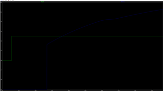
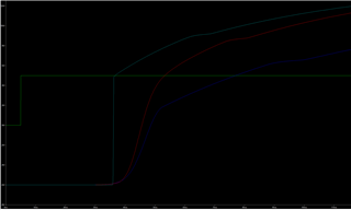
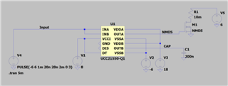
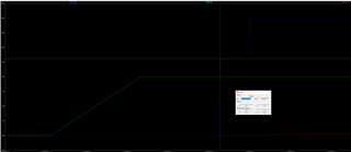
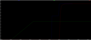
Finally, in the rare instances it does work, the output seem odd. The output(OUTA/OUTB when connected to a FET) will instantly jump 9V in 2 time steps(~2ps) then take ~100ns to climb the last few volts following a curve that looks like a capacitor charging. 

I am sure all of these issues are connected, something wrong with the model, unfortunately I dont know if the issues lies in the PSpice model or my conversion, or some other assumption I am making.

Any information would be greatly appreciated!

Errors:

Questionable use of curly braces in "b§e_abmgate yint 0 v={if(v(a)>{vthresh}&v(b)>{vthresh},{vdd},{vss})}"
Error: undefined symbol in: "if([v](a)>(vthresh)&v(b)>(vthresh),(vdd),(vss))"
Questionable use of curly braces in "b§e_abmgate yint 0 v={if(v(a)>{{vthresh}},{{vss}},{{vdd}})}"
Error: undefined symbol in: "if([v](a)>((vthresh)),((vss)),((vdd)))"

Green line is the input to INA, blue line is output OUTA. After 19ns of propagation delay, output jumps from -6V to just over 3V at a seemingly impossible speed before transitioning to a more 'normal' charge curve.

  • Hi Dakota,

    Can you try the attached model instead? Some model versions have more difficulty being translated into LTSPICE than others. We usually use TINA-TI and PSPICE for TI to design the models. We are not allowed to download LTSPICE and test our models since they are a competitor, and therefore we can't to catch these issues beforehand or recreate them ourselves.

    I designed the attached model, and I think that my method is more coherent with traditional spice simulation. If you have issues with this model, I am in a position to help you more. It is a very similar device.

    Best regards,

    Sean

    UCC21550-Q1.lib

  • Hi Sean, thanks for your quick response I really appreciate it!


    It seems to be working much more consistently now. The output still has similar behavior(jumping very quickly at first, then slowly charging the rest of the way) but it does look better. Can you confirm this is what it looks like in your simulation? 
    I am also getting a singularity matrix issue in one of my simulations that I can only seem to fix by removing UCC21550. I think this is an issue on my side though as I am using an isolated ground so the problem might be on my end. I have attached a picture in case you want to look at it.


    Matrix issue


    The cyan line jumps up very quickly before slowly climbing the rest of the way

  • For the matrix issue, maybe put a 1MΩ resistor between the two grounds. Can you send me your IPT00 file? I can see about the rise time.

    The UCC21550 should have an 8ns rise time. I didn't really limit the rise time in the model, so unloaded it looks like it can rise faster. I can try to fix this.

    Best regards,

    Sean

  • What is an IPT00 file? I would be happy to provide it, however I cant find any info online about it.


    I have tried adding a resistor(everything from 1g to 1m) connecting between the two grounds but it hasn't changed anything. I have also tried adding resistors to all the pins of  UCC21550 also to no avail. 


    The exact error is "Singular matrix: check node u7:n006". The thing is, UCC21550 is U4 and the node N006 is not attached to UCC21550 nor U7 so I am not really sure what node is actually causing the issue. By leaving the inputs to INA/INB floating I am able to get a different error "Singular matrix: check node q:u7:3#collector". U7 is an LT1413, but I have had no issue using any other gate driver (they just aren't as good as the UCC21550, hence why I am trying to change them).

    The only other help I can try and provide is these additional error messages:

    Error on line 2535 : .model u4:_s_uvlo_vcb:_s_uvlo_vcb vswitch roff=1e6 ron=1e-3 vh=3.7 vt=5.3 td=0
    * Unrecognized parameter "td" -- ignored
    Error on line 2530 : .model u4:_s_uvlo_vca:_s_uvlo_vca vswitch roff=1e6 ron=1e-3 vh=3.7 vt=5.3 td=0
    * Unrecognized parameter "td" -- ignored
    Error on line 2525 : .model u4:_s_uvlo_b:_s_uvlo_b vswitch roff=1e6 ron=1e-3 vh=1 vt=5 td=0
    * Unrecognized parameter "td" -- ignored
    Error on line 2520 : .model u4:_s_uvlo_a:_s_uvlo_a vswitch roff=1e6 ron=1e-3 vh=1 vt=5 td=0
    * Unrecognized parameter "td" -- ignored

    U4:_u1:vcs1: Missing value, assumed 0V @ DC

    Yes, if you are able to model rise time/max source and sink currents that would be amazing. You have honestly been such a big help and I appreciate all the time you have put into helping me.

  • By IPT00 file you mean the file for the MOSFET I am driving? IPT004N03L
    Its is a built in NMOS, the source file can be found here: https://github.com/metacollin/LTspiceInfineonNMOSLibrary/blob/master/sub/OptiMOS_30V_LTSpice.lib
    The parameters to it are:

    .SUBCKT IPT004N03L drain gate source Tj Tcase PARAMS: dVth=0 dRdson=0 dgfs=0 dC=0 Zthtype=0 Ls=1.5n Ld=2n Lg=3n

    .PARAM Rs=201u Rg=3 Rd=20u Rm=63u
    .PARAM Inn=150 Unn=10 Rmax=0.4m gmin=119
    .PARAM RRf=500m Rrbond=3m Rtb=2.6 g2=999m
    .PARAM act=23.58 Rsp=3

    .FUNC Pb(I,dT,Rb) {Rb/(2*Rtb)*(I-limit(dT/(max(I,1n)*Rb)+RRf*I*g2,0,I))**2}

    X1 d1 g s sp Tj S5_30_g1_var PARAMS: a={act} Rsp={Rsp} dVth={dVth} dR={dRdson} dgfs={dgfs} Inn={Inn} Unn={Unn}
    +Rmax={Rmax} gmin={gmin} Rs={Rs} Rp={Rd} dC={dC} Rm={Rm}
    Rg g1 g {Rg}
    Lg gate g1 {Lg*if(dgfs==99,0,1)}
    Gs s1 s VALUE={V(s1,s)/(Rs*(1+(limit(V(Tj),-200,999)-25)*4m)-Rm)}
    Rsa s1 s 1Meg
    Ls source s1 {Ls*if(dgfs==99,0,1)}
    Rda d1 d2 {Rd}
    Ld drain d2 {Ld*if(dgfs==99,0,1)}
    Rsb source s1 10
    Rga gate g1 10
    Rdb drain d2 10

    G_TH 0 Tb VALUE = {Pb(abs(I(Ls)),V(Tj,Tcase),Rrbond*(1+(limit((V(Tb)+V(Tj))/2,-200,999)-25)*4m))}
    Cthb Tb 0 10.97m
    Rthb Tb Tj {Rtb}
    Rth1 Tj t1 {1.12m+limit(Zthtype,0,1)*409.35u}
    Rth2 t1 t2 {15.26m+limit(Zthtype,0,1)*5.65m}
    Rth3 t2 t3 {54.01m+limit(Zthtype,0,1)*2.34m}
    Rth4 t3 t4 {60.62m+limit(Zthtype,0,1)*65.25m}
    Rth5 t4 Tcase {142.24m+limit(Zthtype,0,1)*153.1m}
    Cth1 Tj 0 164.143u
    Cth2 t1 0 916.713u
    Cth3 t2 0 5.221m
    Cth4 t3 0 4.155m
    Cth5 t4 0 120.307m
    Cth6 Tcase 0 30m

    .ENDS

  • Thanks Dakota,

    I will try and simulate with this FET model. Could you send a screenshot of your whole circuit? I can't open LTSPICE files due to copy rights.

    Best regards,

    Sean

  • Hi Dakota, 

    I am having trouble getting these FET models to import. It looks like they are bundled together and are not self-sufficient. 

    Can you try running this simulation with a default FET model, or even a voltage controlled switch? These FET models might be too complicated to work with my model and converge into a useful result.

    Best regards,

    Sean


  • Simulation with only the gate driver. I still am unable to simulate it along with any other ICs as having it in my simulation causes everything else to act strange. I also got error while running this sim:

    Error on line 1545 : .model u1:_s_uvlo_vcb:_s_uvlo_vcb vswitch roff=1e6 ron=1e-3 vh=3.7 vt=5.3 td=0
    * Unrecognized parameter "td" -- ignored
    Error on line 1540 : .model u1:_s_uvlo_vca:_s_uvlo_vca vswitch roff=1e6 ron=1e-3 vh=3.7 vt=5.3 td=0
    * Unrecognized parameter "td" -- ignored
    Error on line 1535 : .model u1:_s_uvlo_b:_s_uvlo_b vswitch roff=1e6 ron=1e-3 vh=1 vt=5 td=0
    * Unrecognized parameter "td" -- ignored
    Error on line 1530 : .model u1:_s_uvlo_a:_s_uvlo_a vswitch roff=1e6 ron=1e-3 vh=1 vt=5 td=0
    * Unrecognized parameter "td" -- ignored


  • With CAP set to 200pF

  • Hi Dakota,

    This looks promising. Is this not the expected result? You can ignore the td=0 error, or even delete these terms from the spice netlist if you want.

    Best regards,

    Sean

  • It certainly looks odd. Why does it flatline at 9.5V for about 6ns? The rise time is also faster than the datasheet suggests but this isn't really an issue. Now its just a matter of why it isn't working with my other simulations? Do you have any ideas? I do think the issues lies in the model. 

  • It might be the FET model's way of including the Miller effect. When the Vds falls across the switch, it extracts gate current through the Cds (Crss). 

    I don't know why it is not working in the same LTSPICE circuit as the other models. You might have to use the more simple FET models for now.