This thread has been locked.

If you have a related question, please click the "Ask a related question" button in the top right corner. The newly created question will be automatically linked to this question.

UCC28180EVM-573: Power management forum

Part Number: UCC28180EVM-573
Other Parts Discussed in Thread: UCC25640EVM-020, , PMP31164

Hi TI team

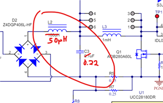
In UCC28180EVM-570 eval board we tried to load the eval board with UCC25640EVM-020 LLC eval board.

We are seeing a uneven waveform (positive cycle is different from negative cycle). Refer attached waveform.

We tried changing ICOMP capacitor value( thought of adjusting current loop) from 2700pF to 1000pF but there is no difference in current waveform.

We are seeing some ringing in the current waveform once after 70W output power ringing vanishnes but the uneven waveform (positive cycle is different from negative cycle) is observed.

Since positive cycle and negative cycle is different even harmonics are more and we could not able to meet DO-160G harmonic standard.

Please help us to get over this issue.

  • Hello Rahamadulla, 

    This is an unusual problem. 

    1.  The screen-shot indicates that for channel 2, the current-probe jaw is not locked shut.  Please make sure the jaw is securely locked before making measurements. 

    2.  Assuming that the open-jaw probe is not the source of the distortion, something about the LLC EVM appears to be unevenly loading the PFC EVM. 
    If you load the PFC EVM alone (with out LLC board) with equivalent load power as the LLC load, does this distortion happen?  If not, then I suggest to investigate the LLC board for the source of the problem.

    3.  Did you make any modifications to the LLC EVM as described in Sections 2.3, 2.4, and 2.5 in the EVM User Guide https://www.ti.com/lit/pdf/sluubx3 (on pages 5, 6)?
    If so, please indicate which changes you made, and examine that they have been made properly according to the instructions. 

    4.  Are you connecting the LLC EVM to the PFC EVM in the manner described in Section 5.3 (on page 12)? 
    Although not listed in the LLC EVM User Guide, the UCC28180EVM-573 should be connected in the same way as shown in Figure 6. 
    For step 4 of the procedure: Connect TP15 (RVCC) on UCC25640EVM-020 to the (+) terminal of J2 (VCC) on UCC28180EVM-573. 

    Don't forget to connect the output GND of the PFC EVM to the input PGND of the LLC EVM. 
    Please review your connections.   

    Regards,
    Ulrich

  • Hi Ulrich

    As per the 4th point you have mentioned the current waveform got smoother.

    I have got one query which is about the input current. At low power less than 70W the current waveform has got distortion near positive and negative zero crossing. If we increase the power level the magnitude of distortion near zero crossing is reduced (Attached waveform). If We try to incraese the frequency to 250kHz the magnitude of distortion near zero crossing is increased more. May i know why it is happening?

    Note:

    Operating frequency is 170kHz

    Boost Inductance: 3.6mH

  • Our required operating power is in the range of 30W to 70W. The waveform is getting more smooth at lower power if we operate at frequency of 250kHz but the zero crossing distortion is problematic getting more and THD is affecting. Please help us to know why that distortion is happening ? that too at high frequency magnitude is more.

    Thanks

    Regards

    Rahamadullah

  • Hello Rahamadullah, 

    The PFC of UCC28180EVM-573 is designed for 360W full load, and 30~70W is >20% of full load.  So PFC performance is not as good at light load as it is at full load.  Also, the inductance on the EVM is suitable for 360W, but is not optimal for 70W. 

    To obtain better PFC results, it will be necessary to design a new 70-W PFC using the Excel calculator tool (https://www.ti.com/tool/download/SLUC506 ) to determine the best values for all of the components.  

    Once the appropriate components are acquired, you can design your own prototype PFC board, or retrofit the EVM (carefully desoldering to avoid damage to the pads), at your discretion. 

    Regards,
    Ulrich

  • Hi Ulrich

    Thanks for your input.

    We have modified the UCC28180EVM similar to PMP31164 reference design except below changes:

    1. Boost inductance 3.6mH (also tested with 1.8mH, 0.9mH)

    2. Frequency 170kHz (also tested with 120kHz,140kHz, 250kHz)

    3. Current sense resistor 0.1ohms for 100W.

    4. Icomp 1000pF

    5. Rvcomp =47Kohm, Cvcomp=4.7uF and Cvcomp,parallel = 47nF.

    We are seeing good results only about 70W (fsw=140kHz) below that input current THD is greater than 10%.

    After trying with increased switching frequency (170kHz and 250kHz) the input current shape is good above 40W but the zero current distortion is dominating as shown in above waveform attached which is deteriorating the THD badly.

    what is the source of this zero current distortion?

    Please help us to avoid the near zero current distortion.

    Thanks

    Regards

    Rahamadullah

  • Hello Rahamullah, 

    I have not worked with 800Hz systems and I am not sure of the source of this oscillation. 

    I am guessing that if higher switching frequency improves THDi at lower Pout, but the current ringing is still prominent then probably the source of the ringing is independent of fSW. 

    I suggest to try changing the differential filter components. If your circuit is like PMP31164 and has L2 and C3, then try changing their values to see if the current ringing frequency and amplitude changes.


    The above change is a suggestion, and other values can also be tried to see what happens. 

    Another suggestion is to make sure that your MOSFET is not oversized for the job.  If it is too big, it will have high Coss which adds turn-off delay and too much peak current will flow per switching cycle, until the loop can compensate for it.
    At 800Hz with fSW = 140kHz, there are only 140/0.8 = 175 switching cycles in a line cycle, or ~44 switching's per 1/4 line cycle.  Long turn-off delay at the zero-crossings can over-charge the inductor current once the voltage starts rising and set off the oscillation. 
    Higher fSW may help, but the MOSFET size is the only thing that can substantially affect the turn-off delay. 

    I think that ICOMP does not have much phase margin, even under 60Hz conditions.  It may be worse at 400~800Hz.
    Try using a Type-II compensation network on ICOMP (like that on VCOMP) with capacitor values around 1000~3300pF.
    Unfortunately, I don't have design equations for Type-II on ICOMP, so it will be a trial-and error process to see if performance can be improved.  

    Regards,
    Ulrich