This thread has been locked.

If you have a related question, please click the "Ask a related question" button in the top right corner. The newly created question will be automatically linked to this question.

UCC28951: Synchronous rectifier troubleshooting with UCC28951

Part Number: UCC28951

Hi , we are currently bringing up a 400W PSFB, Vin=150V-800V, Vout=24V using the UCC28951 PSFB controller. 

Currently we have tested at light load and input voltages not greater than 250V. Due to current configuration of the IC,  synchronous rectifier will turn off below ~55W. 

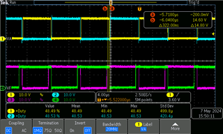
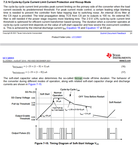
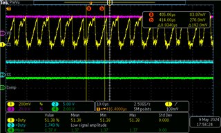
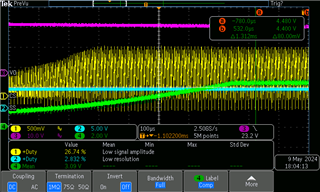
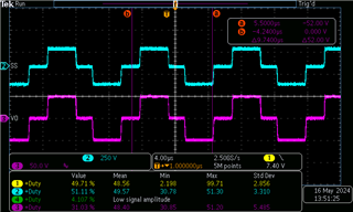
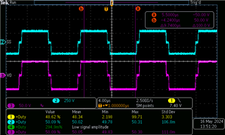
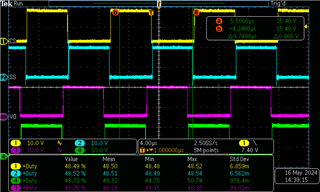
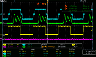
For the conditions we have currently tested, we have seen the converter is able to output 24V and maintain regulation up to 50W, however as we exit the DCM mode and the output drivers turn ON, the output voltages collapses to zero volts. I have checked the waveforms I.E. OutA, OutB, OutE, OutF, and they seem to be in correct sequence. So wondering if you have any suggestion as what can be causing this issue?

  • OUTA (YELLOW)

    OUTB (BLUE)

    OUTE (PURPLE)

    OUTF(GREEN)

  • Hello,

    Your inquiry is under review and we will get back to you shortly.

    Regards,

  • Hello,

    If your output is dropping out of regulation when you turn on the SRs something has occurred to make the controller do this.

    One thing that could do this is triggering over current hiccup mode, which is described below.

    You might want to take a look at CS, Voltage Amplifier Out, SS, Out E, and Out F during this behavior to help determine what is shutting down the controller.  Please note noise on the CS pin can trigger over current protection.

    Regards,

  • hi Mike

    thanks for your reply. I proceeded to probe the CS pin, and you can see here screenshot voltage at CS pin (in green), as well as OUTA and OUTB PWM signals,For a condition where the Vin= 200V and 45W load, Vout was 24V up to this point. At this voltage level, the converter drops out of regulation exactly at 49W when the sync rectifier signals are applied. I also realized by probing all PWM signals, that I dont believe controller is going into hiccup mode, as the controller continues to output all PWM waveforms. Also, CS pin seems to be way below the 2V threshold for overcurrent. 

  • Hello,

    Your inquiry is under review and I will get back to you shortly.

    Regards,

  • Hello,

    These waveform look steady state and the converter is not ready to shut down.  The CS signal looks kind of noisy, however this still would not cause the converter to shut down. 

    If it is not over current hiccup mode shutting down then it is something else that is causing the design to drop out of regulation.  The transformer turns ratio may not be correct.  There could be an issue with your feedback loop.  Your input supply may not be able to supply the output power.   It is important to capture critical waveforms when the design drops out of regulation to help determine what is causing your regulation issue. 

    What you need to do is study the CS signal, voltage amplifier output, SS and Vout.  Triger on when Vout drops out and then look at these waveforms to see what caused the drop out.  You will need to study the waveforms from before the drop out to the dropout.  You can use the zoom in feature of your scope to help with this.  This will help figure out why the converter is dropping out of regulation.

    Regards,

  • hi Mike, ok that's good advice. I probe the signals that you recommended, and trigger upon output voltage falling edge 

    This what i found out, before converter drops out of regulation :

    CS pin looks normal

    Comp pin is at ~ 1.6V

    SS at 4.6V

    Vout=24V

    Then during transient, while converting is dropping out of regulation, 

    CS pin (you can see current magnitude gradually becoming larger)

    Comp pin increasing until it reaches ~ 4.4V

    SS remains at 4.6V

    based on this I suspect I need to take a closer look at the controller compensation values, as somehow the controller is just not able to "compensate" and it rails the output of the error amplifier to it's max. 

  • Hello,

    Your inquiry has been received and is under review.

    Regards,

  • Hello,

    Still working on this and will get back to you shortly.

    Regards,

  • Hello,

    If the comp pin is at 4.4 V the current sense signal should be cycle by cycle limiting to 2 V.  I am no seeing that in your waveforms. 

    You need to trigger on Vout and look back at CS, Comp, SS and Vout to figure out why Vout is dropping out.

    Regards,

  • hi Mike, here is an update. I disabled the SR by removing the GD resistors, so the output fets are just used as passive rectifier. I realize the issue may not be directly related to the synchronous rectifier, but rather something else since the converter is still dropping out of regulation while only in DCM mode (since Sync are off). 

    Furthermore i have a question regarding the behavior of this controller. At 200Vin, and 30W, and Vout=24V (converter is in regulation), The transformer voltages look as shown below:

    Channel1 is primary voltage

    Channel2 is secondary voltage measured w/reference to center tap. 

    now load is increased to 50W, and transformer voltage approaches squarewave shape. As load increases the voltage across the transformer is approaching square wave even more. And this corresponds with OUTA,OUTC only overlapping for a smaller portion, 

    Channel 1, out A, Channel 2 out B, Channel 3 out C, channel 4, out D. 

    here is my question, if Transformer is approaching squarewave, my understanding is that controller is likely demanding 100% duty cycle??

    but what are some reasons that this can happen , since as per calculation given transformer turns ratio and Vin min, I would expect Dmax to be no more than 0.7. 

    I double check my calculations with the XLS tool provided in the TI website here  , this pretty captures our design as it stands currently, even the compensation values match. 

    DEsign Calcs SLUC222D 5-13-2024.xls

    also, here is another piece of information that puzzles me, I probe the drain to source voltage of the output rectifier (for now always in DCM mode), and It oscillates at about 1MHZ. I tried snubbing it out , with a simple RC snubber in parallel but so far no improvement., what so ever. I measured my Llk at secondary side to 0.7uH, used regular snubber RC math, back calculted Rc=4.39Ohms, and try C=220pF first, and then 1nF.. in both cases oscillation persist with no change.. any suggestion on how to get rid of this oscillation?

     here channel 4 shows D-S of QE at about 50W

    here channel 4, shows DS of QE at about 30W

  • Hello,

    This is under review and I will get back to shortly.

    Regards,

    Mike

  • Hello,

    When A and D are on at the same and B and C are on at the same time.  You be applying voltage across the transformer.  Your waveforms do look like there 100% duty and if you are not obtaining the output voltage most likely your transform turns ratio is off. 

    You can use the following equation to check your transformer turns ratio.

    Ns/Np = Vout/(Vin*Dmax)

    In regards to your output rectifiers.  To disable them you short the grounds to source not leave them open.  

    If you are in DCM it is possible to get ringing when the body diode conducts and you should be able snub it with the following equation.

    The L will be the secondary leakage inductance.   C is the secondary switch node capacitance.  You can calculate this base on the ring frequency (fr)

    R > or = (L/C)^0.5

    C = 1/(((2*3.14*fr)^2)*L)

    Regards,