I am using this regulator for a project, and the switching frequency is extremely low. The ripple is also terrible, although this is likely a symptom of the lower-than-expected switching frequency.
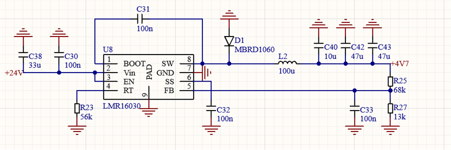
We get +4.7 V out, so it is regulating properly. Here are some screenshots with different loads. Rt is 56 kO, which should correspond to a switching frequency of about 450 kHz. I measured Rt on the PCB, and it is the correct value. I also ensured that it is properly soldered. Again, it is correct. Here are some oscilloscope screenshots with different loads.

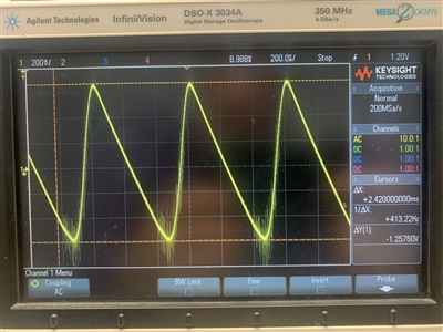
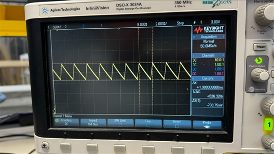
This is with a 49 O load, which means that the load current would be about 97 mA, which is not huge. I will point out that the switching frequency is 303 Hz, and the ripple is 6.7 V.
________________________________________________________________________________
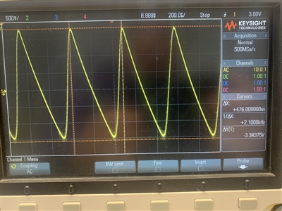
This is with a 204 O load, which means that the load current would be about 23 mA, which is not huge. I will point out that the switching frequency is 526 Hz.
________________________________________________________________________________
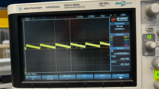
This is with an open load. The switching frequency is 282 Hz.
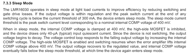
This is not an enormously complicated regulator, and there's only so much that could go wrong. Since the regulator is regulating, it's probably not damaged, but I've never seen this kind of issue before.
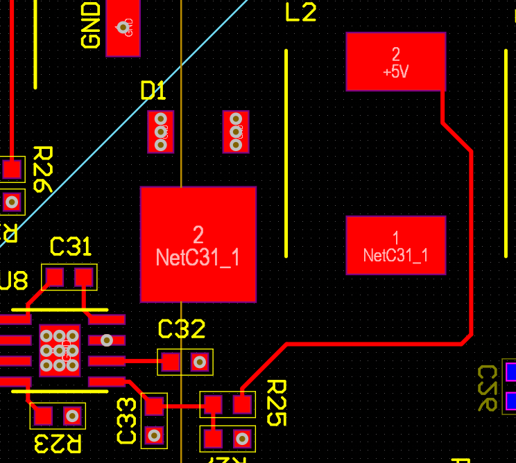
Here is the layout. Note that I've hidden planes for the sake of clarity.