This thread has been locked.

If you have a related question, please click the "Ask a related question" button in the top right corner. The newly created question will be automatically linked to this question.

TPS63811EVM: Error(?) reading register values with Arduino Wire library - register read value is always '0' - but register writes work fine

Part Number: TPS63811EVM
Other Parts Discussed in Thread: TPS63810, USB2ANY, TPS63810EVM, TPS63811

I am using an Arduino MEGA2560_R3 with TPS63811EVM module, communication via I2C (Wire library).  I am able to write to device registers but seem to be experiencing an error reading register values.  Even without being able to read back the register values, I can confirm the register writes work because of outputs changing as expected after reg write.  My simplified my Arduino sketch which demonstrates the problem:

// board jumpers: VSEL pin jumper selects VOUT1 register, EN jumper sets EN_PIN to ON
// external 10k pull-up resistors pigtailed on SDA, SCL I2C lines
// I put some description in the code comments. Hopefully someone can help me fix the problem.

#include <Wire.h>

#define ADDR 0x75     // TPS63811 I2C address
#define CONTROL 0x01  // TPS63811 control register address
#define VOUT1 0x04              // VOUT1 register address
#define VOUT1_RESET 0b0111100   // VOUT1 default bits

/***** using *****
 *  
 * Arduino MEGA2560_R3
 * Wire library (I2C)
 * TI TPS63811EVM
 * 
 */

void setup()
{
  int val;
  uint8_t result = 0x4A;

  /* I am using external 10k resistors */
  pinMode(7, OUTPUT);         // SDA pull-up resistor
  pinMode(8, OUTPUT);         // SCL pull-up resistor
  pinMode(10, OUTPUT);        // TPS63811 VIN

  /* all 5V */
  digitalWrite(10, HIGH);     // power on TPS63811
  digitalWrite(7, HIGH);
  digitalWrite(8, HIGH);

  /***** board jumper settings *****
   * VSEL jumper is set to select VOUT1
   * EN jumper is in the ON position
   */

  Serial.begin(115200);
  delay(1000);

  Wire.begin();
  Wire.setClock(100000);
  delay(1000);

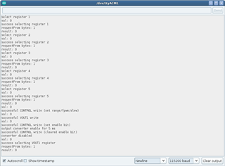
  /* set CONTROL register bits, set RANGE bit prior to setting ENABLE bit (required) */
  Wire.beginTransmission(ADDR);
  Wire.write(CONTROL);          // select control register
  Wire.write(0x4A);             // 0b1001010, 0x4A - sets range bit, fpwm, slew == 5V/ms
  val = Wire.endTransmission();
  if (val != 0)
  {
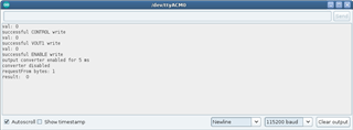
    Serial.println("error writing initial control register value");
  }

  /* set VOUT to desired voltage */
  Wire.beginTransmission(ADDR);
  Wire.write(VOUT1);
  Wire.write(0x64);         // should yield ~ 4.5V with the RANGE bit set
  // Wire.write(0x77);      // 0b1110111, 0x77 - will yield 5.0V when RANGE bit set
  val = Wire.endTransmission();
  if (val != 0)
  {
    Serial.println("error writing to vout1 register");
  }

  /* set ENABLE bit in CONTROL register - enables the converter */
  Wire.beginTransmission(ADDR);
  Wire.write(CONTROL);
  Wire.write(0x6A);         // 0b1101010, 0x6A - sets range, enable, fpwm and slew bits (converter gets enabled)
  val = Wire.endTransmission();
  if (val != 0)
  {
    Serial.println("error setting enable bit in control register");
  }
  else
  {
    Serial.println("output converter enabled for 10 seconds");
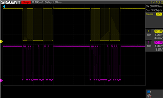
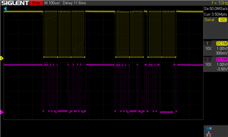
    delay(10000);                   // load (LED+resistor) connected to VOUT/GND - LED illuminates properly for 10 seconds
    Wire.beginTransmission(ADDR);
    Wire.write(CONTROL);
    Wire.write(0x4A);               // clears the enable bit, disabling the converter
    val = Wire.endTransmission();   // LED goes dark as it should
    Serial.println("converter disabled");
  }

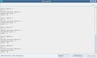
  /* Everything above works.  I have confirmed 4.5V output if I write 0x64 to VOUT1 register.
   * I have confirmed 5.0V if I write 0x77 to VOUT1 register.  Converter is enabled/disabled as expected
   * when setting/clearing the ENABLE bit in the CONTROL register...
    
   * but when I try reading any register value I always get '0' - doesn't matter which register I select,
   * they all return 0.  I have tried all sorts of things but I can't get it to work.
   * 
   * I read this in the TPS6381x datasheet (section 8.5.2) - 
   * "Attempting to read data from register addresses not listed in this section results in 00h being read out."
   * 
   * that would explain my problem excecpt that I have checked all my addresses repeatedly (to the point of absurdity)
   * and they are all correct.
   */

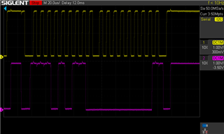
  /***** this read fails - I don't know why *****/
  Wire.beginTransmission(ADDR);
  Wire.write(VOUT1);          // select VOUT1 register
  Wire.endTransmission();
  Wire.requestFrom(ADDR, 1);
  if (Wire.available() == 1)    // I get one byte of data as I should
  {
    result = Wire.read();
  }
  Serial.print("result:  ");
  Serial.println(result);     // but that byte is always is 0
  Wire.end();
}

void loop()
{
  Serial.print(".");
  delay(1000);
}

  • Hi Brian,

    I have not encountered similar problems before, could you try with GUI of TPS63810 and see what will happened? link for GUI followed.

    www.ti.com/.../TPS63811

    BRS

    Tao

  • Hi Tao,

    I don't have a USB2ANY adapter so I am unable to try the GUI software.  I just use pins 9 and 10 on the J3 header for the I2c with my Arduino.

    I do have a TPS63810EVM (dual voltage - non programmable) and thought to give it a try.  The 63810 isn't programmable like the 63811, but I wired it to my Arduino without altering the code.  Register writes fail for the 63810 (this is expected) but I get a successful register read on VOUT1 == 0x4A.

    *edit - error in my example sketch initially assigns result = 0x4A, but should be result = 0.

    See the attached screenshot with annotations.  I ran the sketch on 63811 first where you can see the '0' return and then 63810 second where you can see 74 (0x4A).  I ran them consecutively so the results are in the same serial output window.  I can scope it when I have more time but right now I have to ask - do I likely have a bad 63811EVM ?

    ugh... I can't get my screenshot to display so I'll manually type the output -

    output converter enabled for 10 seconds
    converter disabled
    result: 0                                                         <-- this is TPS63811
    ..........
    error writing initial control register value
    error writing to vout1 register
    error setting enable bit in control register
    result: 74                                                       <-- this is TPS63810, 74 == 0x4A == 0b1001010
    ........

  • Hi  Brian,

    I am sorry i am afraid i can not give you helpful suggestion about this case.

    May be you can capature the waveform of SDA and SCL to see what happened from your side.

    Regards

    Tao

  • First I need to clarify that I was wrong stating that TPS63810 register read was working.  Register reads do not work for either 63810 or 63811 modules.

    Still, register writes do work for TPS63811EVM.  I captured some waveforms of TPS63811EVM.  The first attached shows a bigger picture.  Captures that follow are zoomed, particularly focused on the SDA line dropping to -2.0V (yes, negative) prior to the attempted read.  In the images:

    SCL - yellow

    SDA - purple

    and voltage range is ~ 0-5V.

    Not sure why the sharp negative voltage spike.

  • Hi  Brain,

    Good to hear.

    For spikes, it depend on you actual system, Such as a large parasitic inductor in your SDA cable or not suitable set-up for your test system. But, it is very sure that root cause of this spike is not device itself.

    Regards

    Tao

  • Tao,

    Ok, so I wired a logic level shifter (bob12009) for the I2C, though it isn't strictly necessary, swapped the 10k resistors for 8.2k and triggered on a soft Arduino reset rather than initial power on.  Seems the spikes were mostly due to triggering immediately after Arduino power on.  I modified the Arduino sketch to be a bit more verbose, added some missing return value checks, and cut vout enabled duration to 5ms so I could capture the entire sketch execution on a single screen.

    Everything works, but I still get 0 as a return value when reading VOUT1 register at the end of execution.  It should be readable, right?  I still don't understand why I get 0.

    waveforms shown:

    1. entire execution

    2. working register writes (early)

    3. disable vout (clear enable bit), select VOUT, requestFrom, check available, read

    4. reading VOUT resulting in 0

    5. Arduino serial monitor output (showing no errors for function returns)

    Any thoughts?

  • Hi Brian,

    Vout1 should be readable, that is correct.

    is it possible that you set output voltage control register to VOUT2?

    Regards

    Tao


  • Hi Tao,

    I checked and it is set correctly.  As I mentioned above, I'm unable to read any registers not just VOUT1.  I added a simple function to loop through the registers and you can see each returns a read value of 0.

    amended code

    #include <Wire.h>
    
    #define ADDR 0x75     // TPS63811 I2C address
    #define CONTROL 0x01  // TPS63811 control register address
    #define STATUS 0x02   // TPS63811 status register address
    #define DEVID 0x03    // device ID register address
    #define VOUT1 0x04              // VOUT1 register address
    #define VOUT2 0x05              // VOUT2 register address
    #define VOUT1_RESET 0b0111100   // VOUT1 default bits
    #define VOUT2_RESET 0b1000010   // VOUT2 default bits
    #define SDA 20    // data line
    #define SCL 21    // clock
    
    #define DEBUG
    
    int val;
    uint8_t result = 0xFF;
    
    void wire_read(uint8_t reg)
    {
      result = 0xFF;    // reset to error value
      Wire.beginTransmission(ADDR);
      Serial.print("select register ");
      Serial.println(reg, HEX);
      Wire.write(reg);              // select register
      val = Wire.endTransmission();
      Serial.print("val: ");
      Serial.println(val);
      if (val != 0)
      {
        Serial.print("error selecting register ");
        Serial.println(reg, HEX);
      }
      else
      {
        Serial.print("success selecting register ");
        Serial.println(reg, HEX);
        val = Wire.requestFrom(ADDR, 1);
        Serial.print("requestFrom bytes: ");
        Serial.println(val);
        if (Wire.available() == 1)
        {
          result = Wire.read();
        }
      }
      Serial.print("result: ");
      Serial.println(result, HEX);
    }
    
    void setup()
    {
      // int val;
      // uint8_t result = 0xFF;
    
      pinMode(7, OUTPUT);
      digitalWrite(7, HIGH);
      pinMode(8, OUTPUT);
      digitalWrite(8, HIGH);
    
      pinMode(10, OUTPUT);
      digitalWrite(10, HIGH);   // power on TPS63811
      Serial.begin(115200);
      delay(1000);
    
      Wire.begin();
      delay(1000);
      Wire.setClock(100000);
      delay(1000);
    
    #ifdef DEBUG
    wire_read(CONTROL);
    wire_read(STATUS);
    wire_read(DEVID);
    wire_read(VOUT1);
    wire_read(VOUT2);
    #endif
    
    ... (rest of code omitted)

    serial output

    I'm out of ideas for now :(

    I appreciate all your help.

    Regards,

    Brian

  • Hi Brian,

    I really try to help, but this issue is out of my skill. All i am sure is that we do not have read issue from our side.

    My apologize.

    Regards

    Tao

  • Tao,

    I understand.  I appreciate your effort trying to help resolve this issue, thanks.

  • Hi  Brian,

    Thanks for your understanding, that is nice. Hope you will figure out root cause soon.

    Regards

    Tao

  • Tao,

    Could this behavior be caused by internal damage?  I ask because when running a common I2C scanner (I modified it a little) on my 63810 module I can't even get an ACK.  My 63811EVM is found however.  I don't change anything other than the boards.  It's possible I messed up on my wiring early on and put 3.3v where it didn't belong.

    tps63810

    TPS63810

    tps63811

    63811

  • Hi Brian,

    is it possible you can send EVM to me? then i can check if there is something goes wrong with device.

    Mostly, i do not think device has been damaged internally.

    Regards

    Tao

  • Yes, I sent you a dm asking about where to send.

    Thanks,

    Brian

  • Hi  Brian,

    Please check your PM, i sent your info of address. THX.

    Regards

    Tao

  • Hi Tao,

    I was able to get an ACK when scanning with TPS63810 connected (more on that below), so I am going to hold off on sending the boards  since it appears you are correct that the problem is not the EVM's, but rather I have some serious wierdness going on with my setup.  I am inclined to believe the boards will test good.

    I thought I would mention what prevented my TPS63810 from being found by an I2C scanner with the I2C appearing completely dead, in case anyone else encouters this problem.  Originally, I had SDA and SCL pullup resistors tied to Arduino pins 7 and 8, set pin mode to OUTPUT and drove the pins HIGH - I did measure 5V on them.  But the I2C scan fails to find TPS63810 with this configuration.  Wiring the pullups to the dedicated 5V Arduino pin instead I get an ACK.  Oddly, TPS63811 will ACK with the pullups wired to pins 7 and 8.  I don't know if it is due to noise/emi (pins 7 and 8 are digital/pwm), but since they are HIGH they really shouldn't be getting clipped.

    I still only get register reads returning 0, but I think it is best to shut this discussion down for now since I believe you are correct that the problem lies on my end.  I'll continue to debug and report back if I find the issue.

    Thanks,

    Brian

  • Hi  Brian,

    Thanks for your understanding, hope you can figure out root cause quickly.

    Yes, since i can not help to your case, let us close this thread.

    Regards

    Tao

  • I revisited this earlier today and finally succeeded in reading the registers.  If I use 'endTransmission(false)' prior to reads it works.  The endTransmission() parameter defaults to true.  Setting the parameter false signals to not generate a STOP condition.  Setting the parameter false is only necessary for reads Thinking.  I'm not sure if this is the expected behavior but it is working... finally :)

    Latest code snippet and screenshot below.  *note - I disabled the Arduino internal pullups but had appropriate external pullups.

    #include <Wire.h>
    
    const uint8_t ADDR = 0x75;      // TPS6381x I2C address
    const uint8_t CONTROL = 0x01;   // TPS63811 control register address
    const uint8_t STATUS = 0x02;    // TPS63811 status register address
    const uint8_t DEVID = 0x03;     // device ID register address
    const uint8_t VOUT1 = 0x04;     // VOUT1 register address
    const uint8_t VOUT2 = 0x05;     // VOUT2 register address
    
    const uint8_t VOUT1_RESET = 0b0111100;    // VOUT1 default bits
    const uint8_t VOUT2_RESET = 0b1000010;    // VOUT2 default bits
    const uint8_t REG[6] = {0x01, 0x02, 0x03, 0x04, 0x05, '\0'};
    
    #define SDA 20
    #define SCL 21
    #define DEBUG
    
    uint8_t wire_read(uint8_t reg)
    {
      int val = 0xFF;
      uint8_t result = 0xFF;          // set to error value
    
      Wire.beginTransmission(ADDR);
      Serial.print("select register ");
      Serial.println(reg);
      Wire.write(reg);								// select register
      val = Wire.endTransmission(false);			// don't generate a STOP condition - this works :)
      Serial.print("val: ");
      Serial.println(val);
      if (val != 0)
      {
        Serial.print("error selecting register ");
        Serial.println(reg);
      }
      else
      {
        Serial.print("success selecting register ");
        Serial.println(reg);
        val = Wire.requestFrom(117, 1);         // 0x75, 117
        Serial.print("requestFrom bytes: ");
        Serial.println(val);
        if (Wire.available() == 1)
        {
          result = Wire.read();
        }
      }
      return result;
    }
    
    void setup()
    {
      int val = 0xFF;
      uint8_t result = 0xFF;
    
      //pinMode(7, OUTPUT);
      //digitalWrite(7, HIGH);
    
      Serial.begin(115200);
      delay(1000);
      Wire.begin();
      delay(1000);
      digitalWrite(SDA, 0);
      digitalWrite(SCL, 0);
    
    #ifdef DEBUG
      for (int i=0; i<6; i++)
      {
        Serial.println();
        result = wire_read(REG[i]);
        delay(500);
        Serial.print("result: ");
        Serial.println(result);
      }
    #endif
    
    rest of code omitted...

    Thanks Tao for all your help.  You were very patient with me and helpful/supportive.  I appreciate that a lot - thank you.

    Regards,

    Brian

  • Hi   Brian,

    Instead watching your debug, i really hope i can give you some helpful suggestions. Unfortunatly, it is  out of my skill, i am forcus on hardware only.Joy

    Thanks for your great job and wish everything goes well for you.

    Regards

    Tao