Other Parts Discussed in Thread: , TEST2
LM3409 Debugging Record
Test 1
Test conditions
|
Vin |
10.3V |
|
|
Vadj |
0.2V |
|
|
PWM frequency |
30Hz/5kHz | 10% duty cycle, Vp-p=5V |
LED information
Positive voltage drop (single lamp)=2.6~3.0V
Forward current=5-100mA
Number of series connections: 2
phenomenon
oscilloscope
Ch 1 yellow PWM control signal
Ch 2 blue LED positive voltage
Ch 4 Green LED Luminescence Response (Using PD Test)
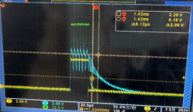
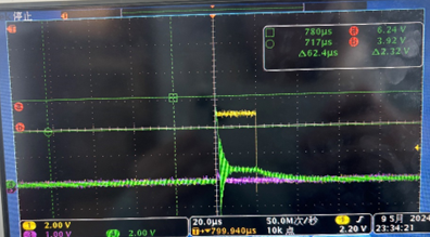
①30Hz switching frequency waveform
② 5kHz switching frequency waveform

Problems that occurred:
1. The ripple problem is quite serious. Are there any measures and suggestions to reduce the ripple?
2. After the frequency increases, the LED shuts off and causes tailing, resulting in severe LED afterglow. Is there any way to improve it?
Test 2
Test conditions
Vin 10.5V
Vadj 0.2V
PWM frequency 30Hz/5kHz 10% duty cycle, Vp-p=5V
LED information
Positive voltage drop (single lamp)=2.6~3.0V
Forward current=5-100mA
Number of series connections: 2
phenomenon
oscilloscope
Ch 1 yellow PWM control signal
Ch 2 blue LED positive voltage
Ch 4 Green LED Luminescence Response (Using PD Test)
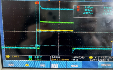
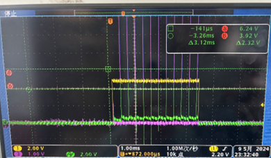
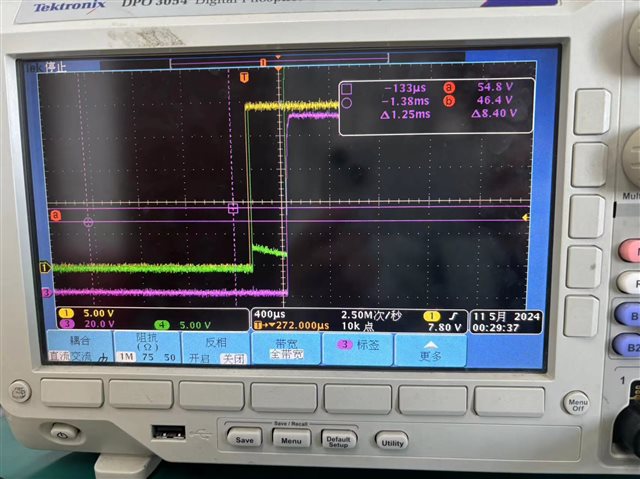
① 30Hz switching frequency waveform

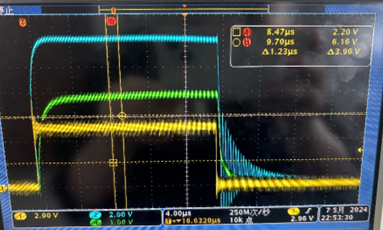
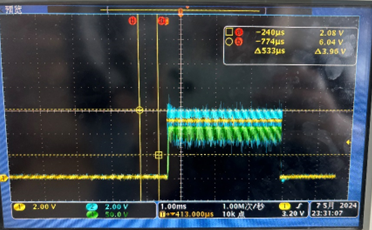
② 5kHz switching frequency

Problems that occurred:
At 30Hz, there is a 300us delay in the LED voltage compared to the control signal. During the delay period, the LED positive electrode has a smaller level, similar to the phenomenon of pre opening. After increasing the frequency to 5kH, this phenomenon disappears
At 5kHz, the falling edge of the LED response oscillates and produces afterglow
3. There are no significant ripples, which is significantly different from the phenomenon in test1
Please help provide solutions to all the above issues. Thank you!