This thread has been locked.

If you have a related question, please click the "Ask a related question" button in the top right corner. The newly created question will be automatically linked to this question.

TPS7B86-Q1: The Delay Pin behavior is different with datasheet said.

Part Number: TPS7B86-Q1

Hi Team,

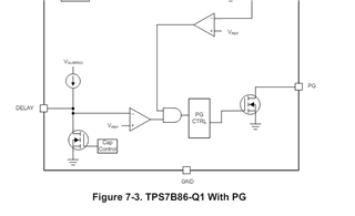
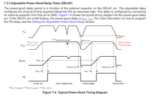
From the datasheet description, when the output is normal, the Delay will keep high, just like below picture shows:

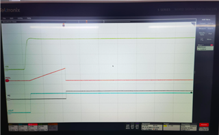
But when I use the EVM to have a test, I find the Delay pin will pull low when it meet the rise up threshold(1.2V), that is a expected behavior for you? Thank you.

Best Regards,

Kunyue

  • Hi Kunyue,

    What connections do you have on the DELAY pin -- do you have a capacitor populated, and if so, what value?

    Also, I can't tell by the image, is PGDL AC-coupled?

    Regards,

    Kelsey

  • Hi Kelsey,

    Yes, I have a 10nF cap in the DELAY pin, the PGDL is the DC-coupled, and it seems that it will go to low in the normal condition, and the cap controller will pull it low, right?

    Best Regards,

    Kunyue

  • Hi Kunyue,

    Thanks for the details. There is some logic involved in the DELAY signal that I need to verify with the designer of this device, then I will get back to you on if this is expected behavior. You can expect an update within the next 2 days.

    Regards,

    Kelsey

  • Hi Kunyue,

    Feedback from the designer is that the behavior you're observing is expected. The delay capacitor is discharged and held in a discharged mode after it is used to implement the delay. This is done in preparation for the next "power bad" / undervoltage condition, so the delay cap starts from zero charge to implement the desired delay.

    The DELAY waveform in the datasheet is incorrect, and I've submitted a request to update it. Apologies for the confusion this error caused, hopefully this helps clarify.

    Regards,

    Kelsey

  • Hi Kelsey,

    Appreciate so much for your confirm, I am totally understand now.

    Best Regards,

    Kunyue