This thread has been locked.

If you have a related question, please click the "Ask a related question" button in the top right corner. The newly created question will be automatically linked to this question.

TPS65987DDK: TPS65987DDK configuration

Part Number: TPS65987DDK
Other Parts Discussed in Thread: TPS65987

Hi guys,

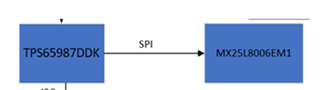
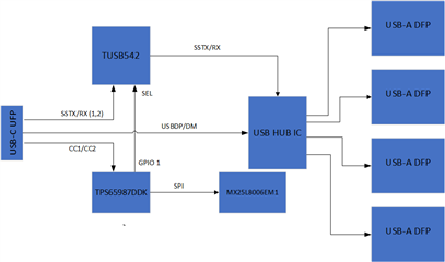
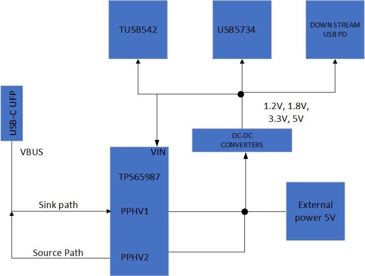
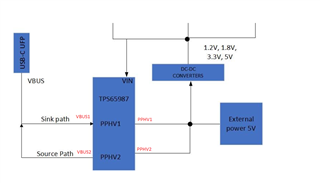
I am designing an USB HUB and I am using TPS65987DDK but I am little bit confused about to configure TPS65987DDK. I know there is a tool to connect to the IC but I am confused how to connect with hardware. I've attached the diagram. I ll use FTDI4232 to flash the firmware to TPS65987. If I design like this, can the tool connect the TPS65987?

Best regards

  • HI Gorkem,

    The FTDI and MicroB is specific to the EVMs and is not necessary to add for customer designs. They are specific to the EVM and are for debug and flash purposes. They should not be included in an actual design.

    I know there is a tool to connect to the IC but I am confused how to connect with hardware.

    Correct, if you are using the EVMs, you can directly connect the EVM to a PC over the micro-B port, and the GUI tool can interface directly with the part.


    In a final implementation, you only need the TPS65987DDK and the SPI flash connected to it.

    In order to flash your boards, you will need to:

    1. Generate the full flash binary using the GUI tool
    2. Directly flash the binary file to the SPI flash(MX25L...) using a SPI Flash programmer.

    Thanks and Regards,

    Chris

  • Dear Chris,

    Thank you for response. Do you have suggestion for the SPI flash programmer? Or Ti has any recommendations?

    Best regards.

  • Hi Gorkem,

    We do not have any official recommendations for a SPI flash programmer.

    Tools that I have used include the TotalPhase Aardvark and the Dediprog SF100.

    Thanks and Regards,

    Chris

  • Hi Chris,

    Do you think if SP200S is suitable?

    Best regards

  • Hi Gorkem,

    I'm not familiar with those device and am not too sure.

    If they are compatible with flashing the SPI Flash you are using, you should be fine though.

    Thanks and Regards,

    Chris

  • Hi Chris,

    Thank you for quick responses. I will let you know if they are working. 

    Best regards

  • Dear Chris, 

    I would be glad if you review my schematics, I've attached it.

    Best regards

    USB-HUB-V3 INPUT.pdf

  • Hi Gorkem,

    What are your system requirements for the USB-C port?

    Is this a 5-V source only?

    Is there an alternate mode?

    Do you need a USB-C PD controller?

    • Are you using power levels exceeding 5V/3A?
    • Are you using alternate modes?
    • USB3 only?

    Are you usind TPS65987DDK  or TPS65987DDH? The schematic says DH, but the E2E says DK.

    Here is feedback on the schematics:

    Must be Fixed:

    • Drain1 and Drain2 should not be connected to each other.
    • Drain1 and Drain2 should not be connected to the VBUS_IN pin.
      • Please see the tps65987dhevm, the DrainX pins are only connected to DrainX pins with the same name(X) and are left floating.
    • LDO1V8 Capacitance should be a max 6uF, you have 10uF
    • VIN3V3 needs ~10uF Bypass cap close to the IC
    • PP_cable needs a 5-V source and bypass cap (10uF)
    • VBUS2 should be tied to VBUS1
    • On the J1 type-C connector, All VBUS pins should be used. Tie A4, A9, B4,and B9 together.
    • each VBUS pin should have a 10nF cap close to the connector pin

    Optional Fixes:

    • ADCINx: you don't need the switch. You can simply use a single pullup resistor and and a single pulldown resistor and manually swap the resistors to change the settings. 

    Thanks and Regards,

    Chris

  • Dear Chris,

    Let me explain to you. I've attached 2 diagrams down there. One of is data other one is power. 

    1- 

    What are your system requirements for the USB-C port?

     It's an 4 port USB HUB and I want it to charge and transfer data when the UFP device has low battery.

    2- 

    Is this a 5-V source only?

    There will be external power 5V. But it will not always on. If there is no external 5V input, the UFP device will supply power.

    3-

    Do you need a USB-C PD controller?

    I have used USB A PD controllers for DFP ports. For UFP, I used TPS65987DDK. These ports are USB 3.1.

    4-

    Are you usind TPS65987DDK  or TPS65987DDH? The schematic says DH, but the E2E says DK.

    I am using TPS65987DDK. Apologies for the schematics.

    Also I would like to share full schematics with you by message but I can't send you a message idk why.

    Best regards.

  • Hi Gorkem,

    Thanks for the info!

    All of the previous feedback still applies. I just labeled some of the port names on your block diagram to make things more clear.

    If you have any more questions about the schematic feedback please let me know.

    For any new questions, feel free to open a new E2E thread!

    Thanks and Regards,

    Chris

  • Dear Chris, 

    Thank you for all of your feedbacks.

    Best regards.

  • Hi Gorkem,

    You're Welcome.

    I will close this thread for now, but feel free to open if you want to continue this conversation.

    Thanks and Regards,

    Chris