This thread has been locked.

If you have a related question, please click the "Ask a related question" button in the top right corner. The newly created question will be automatically linked to this question.

TPS62824: short circuit behavior

Part Number: TPS62824

Dear Team,

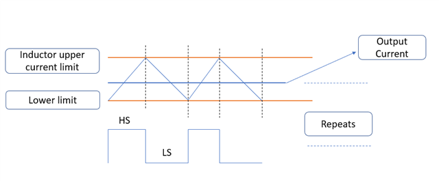
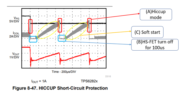
I am designing a circuit that utilizes the TPS62824. My supply is 3V battery and I am aiming for a regulated output voltage of 2.2V. I am particularly interested in understanding the behavior of the TPS62824 under conditions of short circuit and/or overload. How does the TPS62824 react in situations where the output experiences a short circuit  or an overload condition (load exceeding its specified current rating)?

    • What are the estimated output voltage and current values during these events?
    • Will the output voltage completely drop to zero, or will there be some residual voltage?
    • What is the expected behavior of the output current (e.g., will it be limited to a specific value in both scenarios)?

I would appreciate any insights you can provide regarding the TPS62824's behavior in these conditions. This information will be crucial for optimizing the design and ensuring the safe operation of my circuit. Thank you for your time and assistance.

  • Hello Bert,

    Thank you for using E2E, you can find this information in the datasheet under section 7.3.5

    7.3.5 Switch Current Limit and HICCUP Short-Circuit Protection

    The switch current limit prevents the device from drawing excessive current in case of externally-caused overcurrent or short-circuit condition. Due to an internal propagation delay (typically 60ns), the actual AC peak current can exceed the static current limit during that time.

    If the current limit threshold is reached, the device delivers maximum output current. Detecting this condition for 32 switching cycles (about 13μs), the device turns off the high-side MOSFET for about 100μs which allows the inductor current to decrease through the low-side MOSFET body diode and then restarts again with a soft start cycle. As long as the overload condition is present, the device hiccups that way, limiting the output power. In forced PWM devices, a negative current limit (ILIMN) is enabled to prevent excessive current flowing backwards to the input. When the inductor current reaches ILIMN, the low-side MOSFET turns off and the high-side MOSFET turns on and kept on until TON time expires.

    Also please find the measurements in datasheet page-22 

    Figure 8-47. HICCUP Short-Circuit Protection

    Figure 8-48. HICCUP Short-Circuit Protection (Zoom In)

    Let me know if something is not clear.

    Thank you & regards,

    Moheddin.

  • Hello Moheddin, thanks for the fast response but still the behavior is not clear to me. TPS62824 current output range is until 1 A but this ILIM  is very high (2.1 A ?) so i can not clearly understand its mechanism. Also figures are bit tricky to me: if i am not wrong Vout hiccups 0 to 1v and current hiccups between 0-2 A very fast in sawtooth form but it sounds like it is creating a very stressing case for my design instead of protection. Can you elaborate it a bit ?   

  • Hello Bert,

    TPS62824 current output range is until 1 A but this ILIM  is very high (2.1 A ?)

    2.1A is the typical value and typical values are at TJ = 25 °C and VIN = 5 V.

    The min value is 1.7A, considering TJ = -40 °C to 125 °C, and VIN = 2.4 V to 5.5 V.

    ILIM is the peak inductor current value and average output current value will be further less as shown below.

    The switch current limit prevents the device from high inductor current and drawing excessive current from the battery or input rail. Due to internal propagation delay(typically 60ns), the AC peak current can exceed the static current limit during that time. If the inductor current reaches the threshold ILIM, the high-side MOSFET is turned off and the low-side MOSFET is turned on to ramp down the inductor current as shown in the figure. This repeats for  32 times(about 13μs)(A) and then the device turns off the high-side MOSFET(B) for about 100μs which allows the inductor current to decrease through the low-side MOSFET body diode and then restarts again with a soft start cycle(C). As long as the overload condition is present, the device hiccups that way, limiting the output power.

    Thank you & regards,

    Moheddin.