

Hi,
looking at the recommended PCB design, I'm not sure about the via count for connecting the inductor with SW1 & SW2, only 4 via...just don't seems right to me.
I plan to design a prototype PCB, and increase the via count from 4 to 10:
TI recommendation:

My design looks something like this:
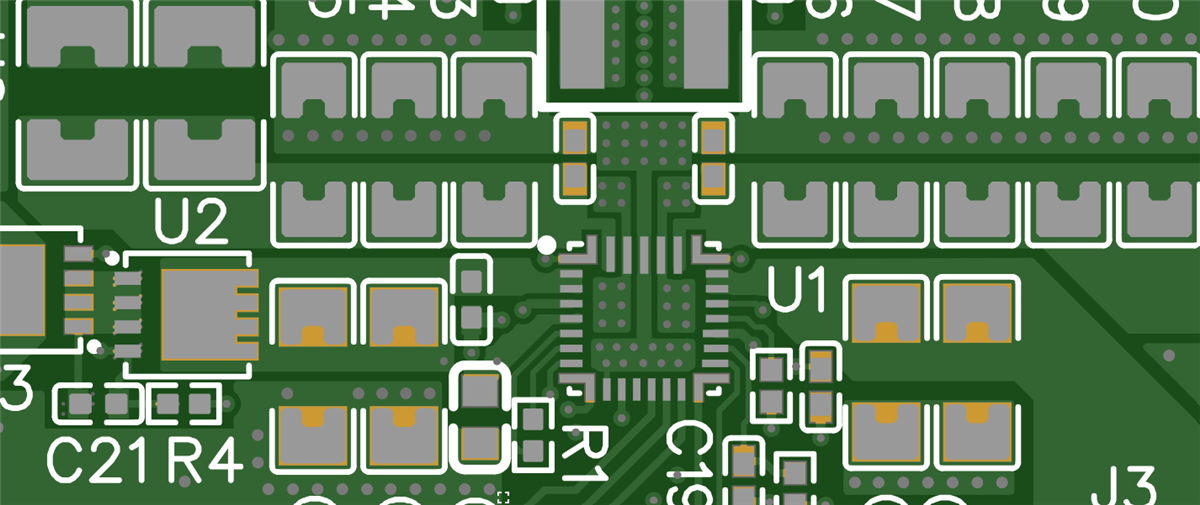
The only thing I'm not so sure about is the GND connection at the IC top part. It is more narrow and far from the IC because of the 4 via supplement.
I do believe that 10 vias would be better than 4 regarding power losses and parasitic induction reduction.
Any thoughts? is this an over kill?
I would appreciate any comments.
Thanks
Nir
