This thread has been locked.

If you have a related question, please click the "Ask a related question" button in the top right corner. The newly created question will be automatically linked to this question.

BQ2973: Please review the schematic

Part Number: BQ2973
Other Parts Discussed in Thread: BQ29700EVM, STRIKE

Dear TI experts,

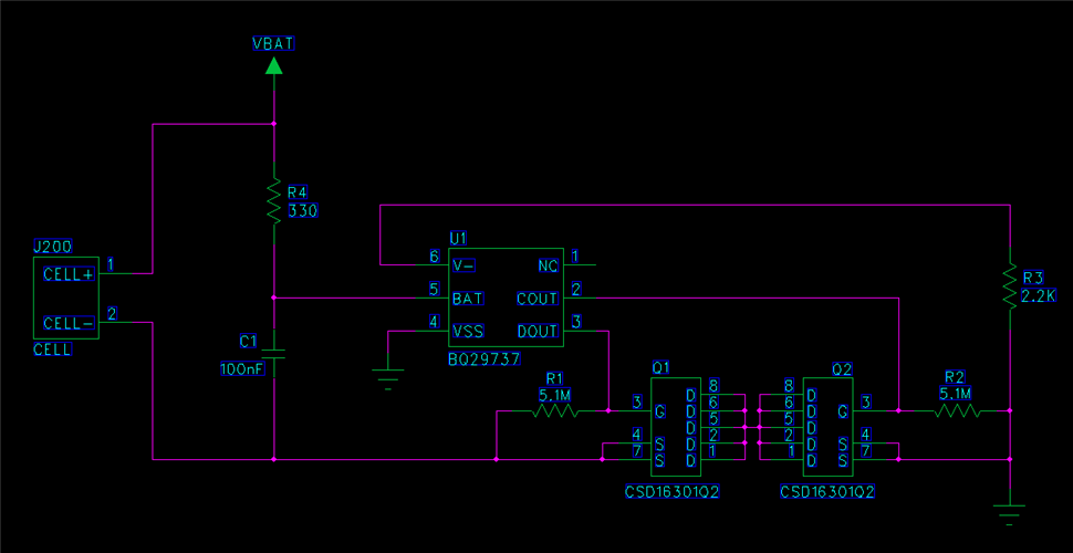
My customer drew their first schematic using BQ29737. Could you review this schematic?

Best regards,

Chase

  • Hi Chase,

    The ground reference in the bottom right of the schematic should be on the battery side of the FETs and connected to the negative terminal of the battery (Cell-).

    Otherwise, looks good!

    Regards,

    Max Verboncoeur

  • Dear Maxwell,

    Thank you for your support.

    Yes, My csuomet will connect GND of bottom right of this schematic to the negative terminal of battery pack.

    And here are another 2 questions ;

    1. I saw "Net-Tie" conponent in the schematic of BQ29700EVM.

    Does it just mean connect Cell- to GND? or any other meaning?

    2. If the answer of no.1 question is Yes, Is okay to connect 2 blue GNDs using either just routing or GND copper? or should I use GND copper to connect these 2 blue GNDs?

    Best regards,

    Chase

  • Hi Chase,

    Right now, the ground reference in the customer's schematic is on PACK-, not CELL-. It's on the wrong side of the FETs.

    GND should always be connected to CELL-, the net tie is optional for ESD protection. 

    This app note explains in depth how the net tie and some added layout considerations can help to protect the IC from ESD strikes: ti.com/lit/an/slua368/slua368.pdf

    To summarize it, having two separate ground pours, one for the high current path (PACK-, through the FETs, and to CELL-) and a low current path (IC ground connections) and connecting them with a net tie allows for routing the ESD strike away from the IC.

    Regards,

    Max Verboncoeur