This thread has been locked.

If you have a related question, please click the "Ask a related question" button in the top right corner. The newly created question will be automatically linked to this question.

TPS922053: Vout

Part Number: TPS922053
Other Parts Discussed in Thread: TPS922055DRRREVM

Dear, 

I am trying to drive two led in serie ILed.fs = 150mA with a PWM input at 70%@194MHz.

Power input Vin should be between [9-36]V.

Unfortunately the Leds can be powered only with Vin@7.3V. If Vin is under or above this value Leds are shuting down.

I probably have a poor understanding of the use of the component. There is also subjects on the component tuning side (Rsense,...).

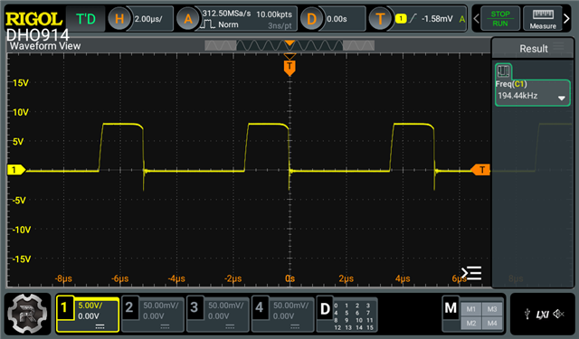
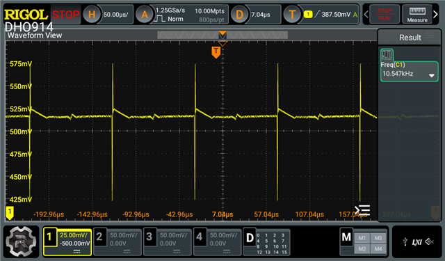
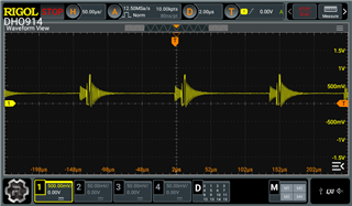
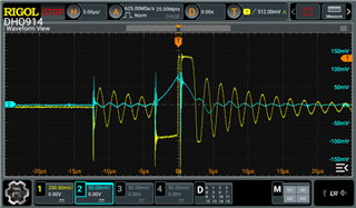
Here is a picture of Vout (Vin@7.3V) probeX10. Vout is a 5.3V and should be at 6.4V.

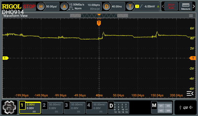
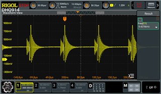
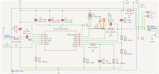
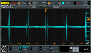
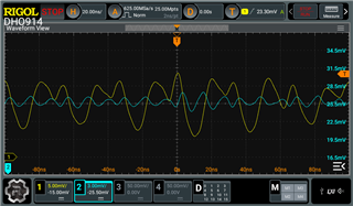
ILed is measured between TP4 and TP6 see shematic below. The value measured is extremely low.

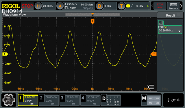
Here is a first picture of the signal ILed:

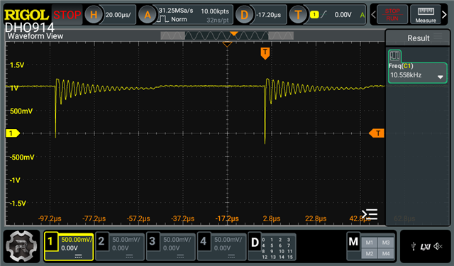
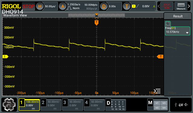
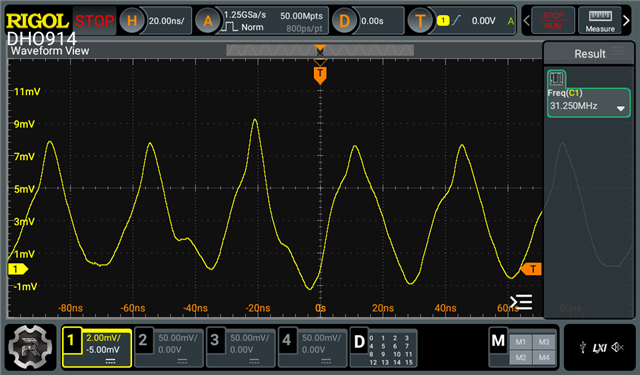
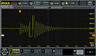
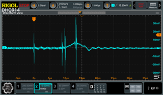
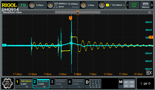
A a second picture with a zoom :


Here is a picture of the schematic :


Thanks in advance for your help.

  • Hi Julien,

    I am trying to drive two led in serie ILed.fs = 150mA with a PWM input at 70%@194MHz

    Please double check if the frequency is 194 "MHz" or not.

    Vout is a 5.3V and should be at 6.4V.

    The forward voltage of your LED will be 6.4V at 150mA. Am I correct?

    Unfortunately the Leds can be powered only with Vin@7.3V. If Vin is under or above this value Leds are shuting down.

    For Vin under 7.3V, most likely the "LED open load" protection is triggered in your circuit. Please leave R10 an R11 open and retry. You can refer to this E2E FAQ - [FAQ] How to design the UVP resistor divider for TPS922055 / TPS922054 / TPS922053 / TPS922052? - Power management forum - Power management - TI E2E support forums

    For Vin above 7.3V, currently I do not have enough information to identify what is happening here. Please measure the SW waveform when Vin = 7.3V and show me the oscilloscope capture. Thanks.

    Best Regards,

    Steven

  • I am trying to drive two led in serie ILed.fs = 150mA with a PWM input at 70%@194MHz

    Please double check if the frequency is 194 "MHz" or not.

    The frequency of PWM is 194kHz and not 194MHz. 

    Vout is a 5.3V and should be at 6.4V.

    The forward voltage of your LED will be 6.4V at 150mA. Am I correct?

    Yes (Vf by LED = 3.2V@150mA).

    Unfortunately the Leds can be powered only with Vin@7.3V. If Vin is under or above this value Leds are shuting down.

    For Vin under 7.3V, most likely the "LED open load" protection is triggered in your circuit. Please leave R10 an R11 open and retry. You can refer to this E2E FAQ - [FAQ] How to design the UVP resistor divider for TPS922055 / TPS922054 / TPS922053 / TPS922052? - Power management forum - Power management - TI E2E support forums

    Unfortunately there is no change when I remove Uvp divider (R10,R11).

    For Vin above 7.3V, currently I do not have enough information to identify what is happening here. Please measure the SW waveform when Vin = 7.3V and show me the oscilloscope capture. Thanks.

    Vin is 8V max after removing the Uvp resistor (R10, R11).

  • Hi Julien,

    Unfortunately there is no change when I remove Uvp divider (R10,R11).

    Sorry for that.

    If you pull EN/PWM pin high all the time, will the shutdown of the LED happen (among all your input voltage range)?

    Best Regards,

    Steven

  • With the EN/PWM pin high all the time (+5Vcc), below 6.4V the brighness of the LEDs is low, at 6.4V the brighness is max. Over 6.4V the brighness is low. If I scope Vout for this last case it seems that the voltage Vout is restricted to 4.2V (see attached picture of Vout).

  • Hi Julien,

    For Vout, do you mean VIN - CSP voltage?

    When you do the above measurement, is there any switching behavior at the SW pin? Please pull up FAULT pin to VCC with a resistor and check the status of FAULT pin at this time. Please show me the oscilloscope capture. Thanks.

    Best Regards,
    Steven

  • For Vout, do you mean VIN - CSP voltage?

    Excuse me for this shurtcut, Vout is measured between Vled+ and Vled-. 

    When you do the above measurement, is there any switching behavior at the SW pin?

    Here is a picture of SW pin when Vin is at 12V (probeX10). The frequency of the signal is 10.5kHz.

    Please pull up FAULT pin to VCC with a resistor and check the status of FAULT pin at this time.

    Here is the status of FAULT pin before the modification (Vin is still at 12Vcc). 

    Here is the status of FAULT pin before the modification (Vin is at 6.4Vcc).

    Then I have pull up FAULT pin to VCC with a resistor of 1.5k. 

    Here is the status of FAULT pin with the modification (Vin is at 12Vcc). 

    Here is the status of FAULT pin with the modification (Vin is at 6.4V). 

  • Hi Julien,

    FAULT pin is an open drain output pin. If you need to use it, you need a pull-up resistor.

    ere is a picture of SW pin when Vin is at 12V (probeX10). The frequency of the signal is 10.5kHz.

    When you do this measurement, do you connect the LED load? If yes, then please provide your LED I-V curve or part number for me to check. Thanks.

    Best Regards,

    Steven

  • When you do this measurement, do you connect the LED load?

    Yes, I connect the LED load. 

    Here is the ref of the LED : MLEAWT-A1-0000-0005DV : https://downloads.cree-led.com/files/ds/x/XLamp-MLE.pdf

    I have two led in serie on the LED board. As you can see p.17 on the curve of the electrical characterics in serie for white led, at 150mA the corresponding  forward voltage in serie is approximately at 11V. I have made an error !!

    I have tested on the bench the led board with a direct power supply Vin@11V and I have gradually increased the current to 150mA. The power supply still stay in CC and the voltage decrease to 6V. The power supply is not a precission power supply so 150mA is approx +/-10mA. 

  • Hi Julien,

    Steven will give you feedback later.

  • Hi Julien,

    I am currently out of office. I will reply to you next Monday. Thanks for your understanding.

    Best Regards,

    Steven

  • Hi Julien,

    Here is the ref of the LED : MLEAWT-A1-0000-0005DV : https://downloads.cree-led.com/files/ds/x/XLamp-MLE.pdf

    I have two led in serie on the LED board. As you can see p.17 on the curve of the electrical characterics in serie for white led, at 150mA the corresponding  forward voltage in serie is approximately at 11V. I have made an error !!

    Sorry but I am a little bit confused. If your LED part number is MLEAWT-A1-0000-0005DV, then two of them in series will give a forward voltage of around 6.4V, but not 11V. Am I correct? Do I miss any point here?

    Best Regards,

    Steven

  • Hi Steven, 

    If your LED part number is MLEAWT-A1-0000-0005DV, then two of them in series will give a forward voltage of around 6.4V, but not 11V. Am I correct?

    Yes, I am also confused MLEAWT-A1-0000-0005DV is a LED designed for parallel mounting. I have miss understood the curves shared in my previous answer. The manufacturer does not recommand to use this LED for a serie mouting as ours.  But we could use this for the developpement. I will probably have to change this ref on a next version.

    As you can see on the table below the temperature Tj have an impact on Vf. But 6.4V is the first value taken.  

    Julien

  • Hi Julien,

    I have tested on the bench the led board with a direct power supply Vin@11V and I have gradually increased the current to 150mA. The power supply still stay in CC and the voltage decrease to 6V. The power supply is not a precission power supply so 150mA is approx +/-10mA. 

    Based on your above description, I tend to think the forward voltage of your LED board is around 6V at 150mA. Please kindly correct me if I am wrong.

    Please do bellow things on your original circuit to help me do the debug:

    • Remove R10 and R11 (leave them open)
    • Change R13 to 0ohm
    • Pull up FAULT pin to VCC pin with a 10kohm resistor
    • Keep EN/PWM pin always logic high
    • Chang C13 to 1uF MLCC // 1nF MLCC
    • Set the input voltage at 9V
    • Measure the SW pin waveform and the inductor current. Then show me the oscilloscope capture.

    Thank you.

    Best Regards,

    Steven

  • I have tested on the bench the led board with a direct power supply Vin@11V and I have gradually increased the current to 150mA. The power supply still stay in CC and the voltage decrease to 6V. The power supply is not a precission power supply so 150mA is approx +/-10mA. 

    Based on your above description, I tend to think the forward voltage of your LED board is around 6V at 150mA. Please kindly correct me if I am wrong.

    You are right. Based on the table transmitted by the manufacturer, at 6V with a Tj of 85°C the current is 150mA.

    Please do bellow things on your original circuit to help me do the debug:

    • Remove R10 and R11 (leave them open)
    • Change R13 to 0ohm
    • Pull up FAULT pin to VCC pin with a 10kohm resistor
    • Keep EN/PWM pin always logic high
    • Chang C13 to 1uF MLCC // 1nF MLCC
    • Set the input voltage at 9V
    • Measure the SW pin waveform and the inductor current. Then show me the oscilloscope capture.

    I have made the modification on the board to make the new test. I have replaced C13 by 1uF electrolitic capacitor I have no MLCC in stock and no 1nF. I will replace them asap.

    I measure 5.5V on Vout when the LED board is connected. 

    Here are several pictures of SW (Yellow curve).

    I did not measure the inductor current. How do you do that. Is it just by scoping the inductor ?

    Regards,

  • Do you know if there is any spice model for the component ? 

  • Hi Julien,

    I have made the modification on the board to make the new test. I have replaced C13 by 1uF electrolitic capacitor I have no MLCC in stock and no 1nF. I will replace them asap.

    Aluminum electrolytic capacitors are not recommended to be used as the output capacitors here for their large ESR. You can use the same 2.2uF MLCC for C13 as you used for C6 to test.

    I did not measure the inductor current. How do you do that. Is it just by scoping the inductor ?

    Yes. You can solder the inductor to the board with a wire and measure the current through the wire with a current probe.

    Do you know if there is any spice model for the component ? 

    Sorry but SPICE model is not available. We can provide SIMPLIS model if needed.

    Best Regards,

    Steven

  • I have made the modification on the board to make the new test. I have replaced C13 by 1uF electrolitic capacitor I have no MLCC in stock and no 1nF. I will replace them asap.

    Aluminum electrolytic capacitors are not recommended to be used as the output capacitors here for their large ESR. You can use the same 2.2uF MLCC for C13 as you used for C6 to test.

    I have removed electrolytic capacitor, it was replaced by 2.2uF MLCC for the test. Vled is still at 5.5V.

    This is SW : 


    I did not measure the inductor current. How do you do that. Is it just by scoping the inductor ?

    Yes. You can solder the inductor to the board with a wire and measure the current through the wire with a current probe.

     I do not have current probe. To measure the current of the inductor, I put a 1ohm resistor in serie between L3 and R14 and I scope the voltage of the resistor. I do not have less than 1 ohm in stock. I will replace this by 1mOhm asap.

    This is I inductor wave form: 


    SW with I inductor : 


    • When I make this measurement I have to remove the Gnd of the SW probe. If I did not the Gnd of the current inductor probe, connected to the 1 ohm resistor, is in contact with the Gnd of the circuit. In this case, I have a new comportement of the LED : Vled is measured at 6.7V. SW and Iinductor are like this :
    • This probably not that we want to do but the brightness of the LEDs are better with this voltage.  
    Do you know if there is any spice model for the component ? 

    Sorry but SPICE model is not available. We can provide SIMPLIS model if needed.

    I do not know this sofware but I could try to do if you send my the model. 

    I do not have bought the dev. board TPS922055DRRREVM. But do you think that could help me to make test in parallel with our LED board? When I have made my shematic, the shematic of the user's guide document was my handbook.

  • Hi Julien,

    Our expert will give you feedback later.

  • Hi Julian,

    Please do bellow things on your original circuit to help me do the debug:

    • Remove R10 and R11 (leave them open)
    • Change R13 to 0ohm
    • Pull up FAULT pin to VCC pin with a 10kohm resistor
    • Keep EN/PWM pin always logic high
    • Chang C13 to 1uF MLCC // 1nF MLCC
    • Set the input voltage at 9V
    • Measure the SW pin waveform and the inductor current. Then show me the oscilloscope capture.

    I did quick simulation for you based on the above parameters - the circuit works fine in simulation. Please let me know if you need this simulation model and I can share it with you through e-mail.

    I do not have bought the dev. board TPS922055DRRREVM. But do you think that could help me to make test in parallel with our LED board? When I have made my shematic, the shematic of the user's guide document was my handbook.

    The EVM may help. But I think there should not be much difference if your board is layout-ed appropriately. Could you show me your layout?

    Best Regards,

    Steven

  • I did quick simulation for you based on the above parameters - the circuit works fine in simulation. Please let me know if you need this simulation model and I can share it with you through e-mail.

    The EVM may help. But I think there should not be much difference if your board is layout-ed appropriately. Could you show me your layout?

    Yes sure, I woud like to see what happens in the simulation. I could share also my layout. Do you have an access to my email? 

    Regards,

  • Hi Julien,

    I have sent you a friendship request on this E2E forum. Please accept it. Then I will send you my e-mail address through private message. Let's continue the talk through e-mail. Thanks.

    Best Regards,

    Steven

  • Hi Steven,

    I sent you an email with attached files. Did you well receive it? 

    Best regards,

  • Hi Julien,

    Yes. I received it and I have replied to you through e-mail.

    Best Regards,

    Steven