This thread has been locked.

If you have a related question, please click the "Ask a related question" button in the top right corner. The newly created question will be automatically linked to this question.

LM5177: 2-Switch Possible? Suitable as Electronic load?

Part Number: LM5177
Other Parts Discussed in Thread: , INA226, LM5171

Hi TI-Team,

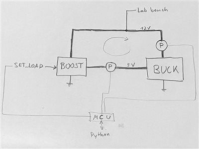
I am looking into using the LM5177 for our test setup, namely we are interested in recycling the power output of our Buck converter (our Device under test). We intend to use this IC in production too, hence possibly running a few hundred of these boards.

The buck's input is 12 V, the Buck output 5V or 3.3V, we hope to have a load of up to 18A, though 10-12A nominal.

  1. Is it possible to use LM5177 as an electronic load to set a load current on the Buck? Is it the most appropriate choice if we intend to sweep the power output of the buck converter, ideally automated by a microcontroller?
  2. Since we only need to boost the voltage, is it possible to omit the Buck-side MOSFETs and HB1 circuit completely and tie Vin directly to the sense resistor, or will the LM5177 not function properly if no devices are connected there? Would we need to connect SW1 in that regard?

Thank you for some clarification!

best regards,

Karim

PS: Just saw the LM51772 but it isn't available anywhere..

  • Hello Karim,

    1. Is my understanding correct that you want to sweep the output current of your buck converter by sweeping the input current of the LM5177? Can you be precise on what you want to use for this?

    2. LM5177 needs the buck side to operate as at startup it is always working in buck mode first as the output capacitors are discharged and need to be charged before going into buck-boost and boost mode.

    Best regards,
    Brigitte

  • Dear Brigitte,

    thank you so much for the fast reply!! So insightful and helpful already.

    1. Yes, exactly. We want to build a test farm where our products shall undergo testing after production. Depending on the test scenario, we would like to apply a higher load on the Buck, and to save energy over the simultaneous testing of hundreds of devices for longer periods, we would like to recuperate the electrical energy. As our buck converter is "dumb", think of a standalone converter, we can only simulate loads by "sweeping the input current of the LM5177", just as you said. I hope that makes sense
    2. Oh, thanks for this insight! The idea is to connect the LM5177 output to the Buck's input (to close the loop), which means that the output capacitors of LM5177 will be precharged. As a precaution, it would make sense to manually control the EN pin of LM5177 from the external MCU that also sets the desired input current to the LM5177. Saving the otherwise unnecessary top side mosfet from the buck half bridge would simplify costs in BOM and reduce losses.

    I hope this makes sense. I would love to see this work out!

    Best regards,

    Karim

  • Hello Karim,

    Let me try to understand what you want to do. It looks very specific to me.

    For the LM5177 to act as a load, it needs a load itself. If there is no load at the output, it will not draw current. So to increase the input current of the LM5177, you need to increase the load on the LM5177, e.g. by keeping the resistance constant and increasing the output voltage, then the power increases.

    If you now connect the LM5177 output to your buck converter, the voltage increases, but this means the input current reduces on the buck, so the load on the LM5177 reduces.

    So I do not understand how this should work.

    Best regards,
    Brigitte

  • Hi Brigitte,

    I am surprised myself that what we want to do is so uncommon and I am very thankful for your help. In my application, we want to create burn-in setups and save the cost of electricity as well as necessary cooling, a process employed everywhere in the production of power supplies, or so we thought...

    As the Buck converter acts as the load of the LM5177, and given the inherent physical nature that energy can only be lost from the system, the maximum power in Watts at the output of LM5177 will always be smaller than the potential load at its input, given steady-state conditions. Without an external power source, the energy cycle will eventually decay. Hence I was searching for LM5177 specifically, as it allows for CC operation, if I understood correctly, whereas the outputted voltage follows the load.

    My idea is to connect the output of the LM5177 to the input of the buck. Set the desired current on the LM5177, then set the desired output voltage of the LM5177 at a little higher than the external power supply voltage (12.1 V in my case). LM5177 will never reach this voltage and regulate its output matching the external load voltage, but supplying the set current.

    Maybe this simple paper sketch helps make sense of my gibberish.. (we also want to measure Power In and Power out, P was used for both ammeter and voltmeter, we have experience with another awesome TI part, INA226...)

    An anecdote (no need to read): At my previous job, albeit two magnitudes higher, we used E&A's ​​Regenerative DC Electronic Loads that convert the output of the Device under Test back into Mains voltage. The Device under test itself operated with DC input, so we had a second Laboratory power supply to provide the DC power from the mains. As both the Laboratory power supply and Regenerative DC Electronic Load were connected to the same power input, we only needed to supply the losses from the grid and were able to test systems over a long period at loads far exceeding the capacity of the grid. In my case, it is not economical and necessary to use isolation and or go back to AC.

  • Hello Karim,

    Ok, I think I understand what you want to do. It might work as long as you command LM5177 to a higher voltage than the lab bench it should load the buck with the current and drive the circle. As long as the lab bench delivers the losses.

    As I never tested this in the lab, I cannot say if it will work in reality.

    For the buck side transistors of the LM5177, I doubt that you can remove them even in this configuration, but I will discuss with the responsible engineer about it.

    Please give me until beginning of next week for getting back to you.

    Best regards,
    Brigitte

  • Thank you so much!! Your reply would probably save us an iteration. Have a nice weekend! Will close the thread afterwards.

  • Hello Karim,

    Thank you and have a nice weekend as well.

    Best regards,
    Brigitte

  • Hi Karim,

    You may have a look at LM5171. I think it may ease your design as you want a constant current control.

    Best Regards,

    Feng

  • Hello Karim,

    I checked with the designer if it is possible to remove the buck switches in this case and he expects that shorting the top switch and leaving the bottom switch open should work.

    As no-one checked this in the lab, I would recommend to having these switches placed in the layout as they should, but then shorting the top one and leaving the bottom one open. (make the short the way that you can cut it easily if needed)

    All the components on the device are still needed.

    The idea of using LM5171 could work as well. As this one is just a boost in one direction and a buck in the other direction which you do not need.

    Best regards,
    Brigitte