This thread has been locked.

If you have a related question, please click the "Ask a related question" button in the top right corner. The newly created question will be automatically linked to this question.

BQ28Z610: Fail Current calibration

Part Number: BQ28Z610
Other Parts Discussed in Thread: EV2400, BQSTUDIO

Hi Everyone.

We have a problem happen on some product related to Calibrate Current.

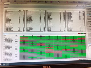
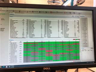
I have capture screen OK case and NG case as bellow picture.

based on the Picture the problem seem related to the charging. But I don't know exactly where is the problem happen.

Do you have any advice for my situation?

Thanks and best regards.

  • Hello, 

    Have you followed the procedure for current calibration outlined in section 11.4 Current Calibration of the bq28Z610 TRM

    Regards, 

    Jonny. 

  • Hi Jonney.

    We follow the procedure for current calibration.

    We use 7.3V, 2 cell serial, and 1A for current calibration. 

    More information, we run this product in Mass production, and the ratio about 0.5%, that mean the issue is not about the procedure of the current calibration.

    As I mentioned in the previous comments, The OK and the NG current calibration only different some bit in Battery register and Gauge status register as bellow:

    -------------------------Battery Statius register comparation--------------------------

    1.OK product: Battery Status Register have a value: 0x0080 ->DSG bit =0

    2.NG Product: Battery Status Register have a value: 0x00C0 -> DSG bit =1 -> Battery discharging.

    -------------------------Gauge Status register comparation--------------------------

    1.OK product: Battery Status Register have a value: 0x10 ->DSG bit =0

    2.NG Product: Battery Status Register have a value: 0x50 -> DSG bit =1-> Charging not Detected

    -------------------------Charging Status register comparation--------------------------

    1.OK product: Battery Status Register have a value: 0x0002 ->IN bit =0

    2.NG Product: Battery Status Register have a value: 0x0012 -> IN bit =1 -> Charge Inhibit Active

    About the design, we follow correctly the TI recommendation. 

    Do you have any advice for this, based on above data?

    Thanks, and best regards.

  • Hello, 

    Please refer to sections 4.13 Charge Inhibit and 4.14 Charge Suspend of the bq28z610 TRM. In your screenshots it looks like the temperature is well above room temp, please ensure you are calibrating in room temp.  

    Regards, 

    Jonny. 

  • Hi Jonny.

    Thank for your respond.

    I have more question about power supply for BQbq28Z610.

    In the datasheet it said that:"Power Supply Requirements There are two inputs for this device, the PACK input and VC2. The PACK input can be an unregulated input from a typical AC adapter. This input should always be greater than the maximum voltage associated with the number of series cells configured. The input voltage for the VC2 pin will have a minimum of 2.2 V to a maximum of 26 V with the recommended external RC filter"

    As my know, we only input the power supply on PACK or VC2 and then we can program or communicate with the BQ use EV2400 that's right?

  • Hello, 

    I am not sure that I fully understand your question here, can you please explain what exactly you are asking here? 

    Regards, 

    Jonny. 

  • Hi Jony.

    I'm sorry if my question make you confuse.

    BQbq28Z610 specification told that: There are two inputs for this device, the PACK input and VC2, so my question is

    In my Schematic (you can see in the previous post) if I only power supply (7.3V) into the VC2 pin, whether I can communicate or program to U1 or not? Because currently I cannot communicate or program to U1 when I power supply into the VC2 pin. The PCBA and U1 was not problem, because when I power supply to the PACK pin, I can communicate and program to U1.

  • Hello, 

    The gauge should turn on when you apply a voltage to the Batt connections. Pease ensure that you wake the device. The EVM has a push button to wake the gauge. 

    Regards, 

    Jonny. 

  • Hi Jonny.

    I have enabled Gauge from EVM several times. But the result didn't change, it still cannot communicate with the U1 when I power supply from Battery.

    are there any advice for this situation?

    Regards.

  • Hello, 

    It looks like you are able to communicate with the gauge based on the image you have provided above. It looks like you are able to read the registers. If you were not communicating with the gauge, the registers page would be all grey and you would not be able to read any values from the gauge. 

    Regards, 

    Jonny. 

  • Hi Jonny.

    I only communicate and read the register when I input Power supply on the PACK Pin.

    But when I input the power supply to the VC2 Pin, I cannot communicate and read the register.

    My question is: If I only Power supply for the VC2, how can I communicate and read the register.

    Regards.

  • Hello, 

    You should be able to power the gauge just through VC2. One thing to note that could be causing this behavior you are seeing is that you need to briefly short BATT+ to PACK+ to wake the device. Please try to power the device through VC2 and then short PACK+ with BATT+ briefly to wake the gauge, then after you have done this try to open bqStudio. You should be able to communicate with the gauge after doing this. 

    Regards, 

    Jonny.