This thread has been locked.

If you have a related question, please click the "Ask a related question" button in the top right corner. The newly created question will be automatically linked to this question.

BQ27427: NTC Curve Generation

Part Number: BQ27427
Other Parts Discussed in Thread: BQ34Z100-G1, BQ27426, BQ40Z50

We’re developing a temperature polynomial curve for use with BQ27427 and NTC. I had a few questions I couldn’t answer from the relevant documents.


  1. When the BQ27427 reads the NTC, it seems to pull the NTC up for around 125ms every second. I’ve seen typical pull-up values of 8.45k(from  SLUA398) and 21k(for BQ34Z100-G1), what does BQ27427 use?
  2. Is the NTC ADC reference for BQ27427 the internally regulated VDD, 1.8V?
  3. Is SLUA398.pdf and corresponding ZIP file the correct reference document for computing a new NTC curve for BQ27427?
  4. How do I map the values from the SLUA398 Excel solver to the BQ27427 registers? For example:
    1. SLUA398 Excel: Polynomials: A0, A1, A2, A3, Min A/D Max Temp
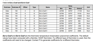
    2. BQ27427 TRM: “Ext a Coef 1-5”, “Ext b Coef 1-4”
  5. Is there a function that takes in ADC counts and Polynomial coefficients and computes temperature that we could use for testing?
  • Hello Justin, 

    The typical pull up should be 10k, and typically this is to 1.8V. For the thermistor coefficients, you can refer to section 7.4.5.1.4 Ext a Coef and Ext b Coef from the bq27427 TRM. 

    Regards, 

    Jonny. 

  • Thanks Jonny,

    > The typical pull up should be 10k, and typically this is to 1.8V. 

    I just want to double check - is that the BQ's internal pull-up resistance? That's a value I haven't seen referenced elsewhere for the internal temperature pull-up.

    > For the thermistor coefficients, you can refer to section 7.4.5.1.4 Ext a Coef and Ext b Coef from the bq27427 TRM. 

    How do we map the outputs of SLUA398's excel calculator(A0, A1, A2, A3, Min A/D, Max Temp) to those you've highlighted in bold? The excel calculator only produces one set of coefficients, do we need an additional set of B coefficients? There's a different number of A-coefficients between SLUA398 and the BQ27427 registers, if we need to zero one of the registers, do you know which one it is?

  • Hello Richard, 

    This excel sheet is for the older devices. Please refer to this E2E thread regarding the thermistor coefficients. 

    Regards, 

    Jonny. 

  • Thanks Johnny, that thread is very helpful.

    Could you please confirm the BQ27427 pull-up resistance, pull-up voltage, and ADC VREF?

    When I replace the 10K NTC with a fixed 10K resistor and measure the pulses on BIN, If I assume the BQ27427 pull-up voltage to be its internally generated 1.8V VDD, then the BQ 27427 internal pull-up must be closer to roughly 17kOhm rather than it is to 10kOhm. But if the internal pull-up is 10K, I don't think the internal pull-up voltage can be 1.8V.

    I noticed that "Analysis_Custom_External_Thermistor_Coeff_NewConfig_20111111.xlsx" uses a 19kOhm internal pull-up, and in https://e2e.ti.com/support/power-management-group/power-management/f/power-management-forum/868181/bq27426-how-to-specify-a-different-external-ntc-100k-3950k Eric Voss states the BQ27426 uses 18K pull-up, might the BQ27427 also use 18K?

  • Hello Richard, 

    Yes the BQ27426 and the BQ27427 are similar devices, the BQ27427 should use the same value for the pull-up resistance as the BQ27426. 

    Regards, 

    Jonny. 

  • Thanks Jonny! I've been able to build a parameterized curve fitter that looks pretty close for my application. But before I loaded my fuel gauge, I decided to try and reproduce the original coefficients using the Analysis_Custom_External_Thermistor_Coeff_NewConfig_20111111.xlsx, and it just doesn't line up. When I read them from the BQ27427 I get the expected values in the TRM. A few notes:

    1. The original spreadsheet claims to be for an NTC103AT, but specs Beta=3900K, while NTC103AT has Beta=3435K, so the resistance values in the spreadsheet seem to be for something else.
    2. When I replace the Temp/Resistance table with that of NTC103AT, and replace the R1 PU with 18K, the error curve is off about 15C.
    3. If I follow Max Naumov's instructions to adjust VRef from 1.8V to 2.5V, it's much closer, but there's still a systemic bias that any curve-fitter should've handled.

    Is there any chance you might have the tool used to create the original coefficients for the BQ27427? I'm just having a lot of trouble reproducing these results, and I know getting the temperature correct is important for Impedance Track's OCV measurements aligned.

  • Hello,

    Jonny is out of office today. Please expect a delayed response.

    Regards,

    Anthony Baldino

  • Hello Richard, 

    The spreadsheet you mentioned is for older devices and is not for the BQ27427 gauge. In the previous E2E thread I had linked, the suggestion was to use a thermistor with the same Beta so that you do not need to change the coefficients to get the temperature accurate for gauging. 

    Regards, 

    Jonny. 

  • Hello Jonny,

    I don't think that will work for our design - we've got a bias that needs adjusted out at the ADC->temperature curve.

    -Richard

  • Hey Richard, 

    You can try the thermistor coefficient tool for the BQ40Z50 to see if this is what you are looking for. There is not a specific calculator tool for the BQ27427 thermistor coefficients. The BQ40Z50 thermistor coefficient calculator tool can be found in this E2E thread

    Regards, 

    Jonny.