This thread has been locked.

If you have a related question, please click the "Ask a related question" button in the top right corner. The newly created question will be automatically linked to this question.

LM63625-Q1: Units short out when VIN raised to 24V

Part Number: LM63625-Q1

I have two proto boards here that I am using LM636265DQDRRRQ1's to generate several rails from automotive (battery) voltage levels (9V-32V).

There are four of these units on each board, generating 3.3D, 5.0D, 5.0A, and 7.2D rails.

I am experiencing faults with the LM63625's.  Back on 8/2021 when the boards were first built, I had one of the 8 regulators fail after 1/2 hour @ 32V.  I replaced the unit and attributed it to early component failure as everything seemed to be in spec otherwise., and both boards passed diagnostics @ 32V in.  The failed regulator was on the 5.0D rail, which has a worst case power draw of 1.2A, typically a little over half of that.

We have been chipping away at the application software, typically running @ 12V.   Yesterday I raised system voltage to 24V to test driving 24V solenoids, and as soon as I raised the input voltage to 24V, the IC on the 5.0A rail shorted.  This rail consumes around 120mA maximum.  I replaced it, and it failed again at raising it to 24V.  I pulled the dead chip off the board, and wired in a benchtop power supply for 5.0A supply, and ran the unit at 32V for over an hour with no failure on the other 3 converters, (minimal load on the 5.0A rail, the bench power supply was reading 0.0 amps).  Soldered in another one, again reading 5V out @ 12V then failing soon after raising system voltage to 24V.

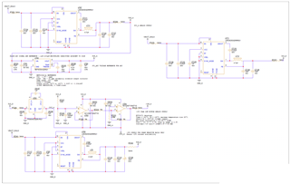
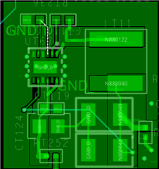
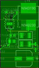
At this point I am concerned that there is something wrong with my design or I have a batch of bad parts.  I have attached the schematic page for the 5V0_A and 5V0_D supplies, as well as the layout used.

The 3V3 and 7V2 layout is a mirror of the 5V0_A layout.  Any ideas why I would be having failures?


  • Here is a high frequency probe of GND:SW of the 5V0_D circuit running @ 32V in.  I don't have the 5V0_A circuit currently populated, but the other rails (3V3, 7V2) look similar to this, only a little over/undershoot.

  • Hi Glenn,

    When you replaced the IC, did you ohm the pins to make sure there was any soft shorts between the pins? I just had another E2E thread where the person had issues where their setup kept blowing up the IC because there was too much solder paste being applied to the IC.  When the unit was soldered down, the exposed pad was shorting to VIN and SW pins causing the IC to have a catastrophic failure. 

    My suggestion is to set a current limit on the power supply to keep the IC from being damaged while VIN is being raised to 24V.

    Ben  

  • In all cases, before power was applied to the board, I checked for shorts from ground to all five non-ground nets that fan out from the IC.

  • What about pin to pin? I dont see an issue with your schematic and layout. Try adding more bulk capacitance on VIN. Do the other rails fail if the input voltage goes up to 24V?

    Ben

  • Problem found.  I installed another LM63625 and the switching node had severe over / undershoot.  After some more troubleshooting I pulled off the inductor and measured with LCR meter, LCR meter was giving inconsistent and unbelievable readings.  Replaced with a new inductor, waveform is OK, unit now operates at 32V.  There is no visible external damage to the inductor, but it is highly likely that the core has an internal crack/flaw.

  • HI Glenn,

    Glad that you have found the issue. If there are no further question, please close the thread by clicking on "resolved". Thanks!

    Ben