Could .you help to review the schematic of BQ24715?
Input voltage 20V, 2 cells Li battery, 2A charging current.
This thread has been locked.
If you have a related question, please click the "Ask a related question" button in the top right corner. The newly created question will be automatically linked to this question.
Hello Fabio,
I don't see any obvious issues with the schematic.
Best Regards,
Christian.
The customer is using BQ24715 to charge two cells battery. 20V input voltage/2A.
But the temperature increase is larger than 50℃ of this chip.
What is the potential reason? It seems there is no place in the cheap which could consume so much power.
Hello Fabio,
Can you confirm that you followed the BQ24715 PCB layout guidelines:
Best Regards,
Christian.
The customer have revised their layout from two layer to four layer.
Could you help to review the layout and give some improvements suggestions?
Thanks
Hello Fabio,
Please allow me time to review the PCB layout. I will provide an update with my feedback by EOD Thursday.
Best Regards,
Christian.
HT-PCB-1321-B2310A-PC-V03.PcbDoc
Hi Christian, the V04 is the four layer layout. The newer one V03 is the two layer layout.
The end customer said four layers is too expensive.
They still want to improve the layout in their original two layers.
Could you help to review the V03 version?
This project is a bit urgent. Can you help me take a look?
Hello Fabio,
Yes, I will review the V03 layout version. I will provide an update after I gather more information.
Best Regards,
Christian.
Hello Fabio,
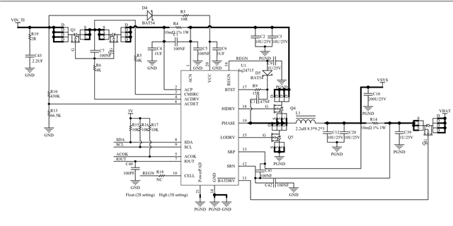
I don't see any obvious issue with the PCB layout. We suggest mulitple copper layers to dissipate heat to reduce the case temperature without these extra layers we don't have any other ways to increase heat dissipation.
Best Regards,
Christian.