


Part Number: TPS4811-Q1
Dear TI team,
I am using your High Side switch TPS48110AQDGXRQ1 as a power switch for radar power amplifiers. The voltage is 45V (although it can be set between 38 and 47), while the expected currents are around 5A, so I set the OCP threshold to 7.95A, and SCP to 10.13A. Please take a look at the schematic.

Given that I have a capacitor bank of 1x10uF + 4x22uF on the power amplifier VDD line, I set an RC filter with values of 100kΩ and 2nF at the gate of the transistor I use as a switch (PU pin). This should correspond to a maximum capacitor charging current of about 4A, while the charging time would be about 1ms for the FET and capacitor bank I chose.
In that case, OCP activation occurred.
I did not immediately use an oscilloscope to check the waveforms but assumed that the reason was the GaN HEMT in the power amplifier, whose gate is set so that its idle current is approximately 1.2A. Therefore, I did the following: first, I increased the RC filter by populating 5.6nF instead of 2nF (before that, I tried with 2.7nF, 3nF, 3.3nF, 4.7nF, and it turned out that with 5.6nF I most often had success, although I also had cases without OCP activation with values from 3.3nF to 5.6nF. I tried with 10nF also, but FET was damaged, not sure that was the reason, but I did not want to go further).
Then, due to the power amplifier's needs, I had to raise the OCP and SCP limits to 13.5A and 14.1A, respectively. This, correct me if I am wrong, should further relax the startup, i.e., reduce the possibility of triggering the OCP. However, the OCP continued to activate.
This happened several times (three, four, five...) after leaving the equipment off for an extended period, but once it passed the initial activation, it worked without problems until the next long pause in testing. I thought the reason was the charging of the capacitor bank, but it was not. I discharged them completely couple of times, and it did not depend on whether it entered OCP or not.
I also checked the temperatures, cooling the entire high switch circuit with freeze spray or heat it, but I would say that did not affect OCP activation either.
Then I used an oscilloscope and recorded the waveforms.
The first plot shows the situation where the OCP does not activate.
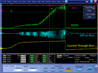
Curve 1 is the current recorded with current clamps, and curve 4 is actually the voltage on the RIMON resistor. Curve 4 has a peak at the beginning, which the actual current does not have. However, due to the duration and amplitude of the voltage, the OCP was not triggered. To add, the OCP is set to shut off the circuit after 51μs once triggered (theoretically).
Note: Diff on Rsns means we measure the voltage with a differential probe on the shunt.

There are oscillations of voltage on Rsns, but I am not sure why. Tried to populate capacitor of 100nF to GND but did not help, there was no difference.
The next graph shows the situation when the OCP is triggered, and the peak lasts for at least 51μs. In this case, it is also seen that there is no such current on the shunt, curve 1, but the voltage on RIMON goes above 3.3V and triggers the OCP, which after 65μs (visible via the cursor on the plot) shuts off the switch.
Do you have any idea why this is happening?
Any suggestions would be greatly appreciated.
One more thing to mention, I tried to change position of the supply cables, other equipment (to be sure that no interferences are happening), but nothing helped.
Once it starts, it works good until next longer pause in testing.
Thank you in advance!
Best regards,
Nenad


