This thread has been locked.

If you have a related question, please click the "Ask a related question" button in the top right corner. The newly created question will be automatically linked to this question.

TPS543B22: About EN_UVLO Design

Part Number: TPS543B22

Hi Team, 

Recently when designing the circuit of TPS543B22, I have some questions about EN_UVLO and I would like to ask for advice.

1.

EN_UVLO Pin in Spec Pin voltage Max is 5.5V,
Use WEBENCH® POWER DESIGNER to design. If you design UVLO START: 3.8V, UVLO STOP: 3.4V, the Enable voltage obtained in the 18V system is 5.79V, which seems to exceed the upper limit. Is this correct?

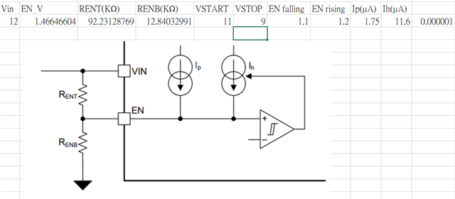
Rent:8.06K,Renb:3.83K

2.

Use WEBENCH® POWER DESIGNER to design.
If you input Min 12V and Max 18V in Vin,
When the EN_UVLO function on the website is turned on, the UVLO_Start display here can be set to a maximum of 12V, Vstart: 12V, Vstop: 10.91V. After calculation by the website, the EN start threshold shows 11.58V.
But isn’t the maximum EN Pin 5.5V? Is this a BUG?

3.

Like Q2, this represents the voltage of the EN Pin. Can it be directly connected to Vin?
EN_UVLO Pin only shows the highest voltage is 5.5V. Is there any protection function inside EN?
If Vin is directly connected to a 12V system, is it feasible without voltage division?

Best regards,

Guanming

  • Hello Guanming,

    Thanks for your interest in the TPS543B22. 

    R1.   Your math is correct but the use case is an edge case and not practical, since there is an internal uvlo on VIN as high as 4.2V max.    

    The TPS543B22 has an internal VIN pin uvlo of 4V typ. start voltage and a hysteresis of 150mV which will gives a 3.85V typ stop voltage.  

    Selecting 3.8V and 3.4V uvlo with external resistors is not needed or possible, since the internal uvlo will override the enable pin status.

    The low impedance source greater than 5.5V can damage the EN pin, but when using the voltage divider with resistors on the

    enable it is not low impedance and considered low risk. 

    R2.   EN UVLO voltage is not the EN pin voltage, but the vin voltage that is set by the Rent, Renb resistors to start the device.    

    The Rent and Renb are connected to the VIN to EN to GND pins.   

    When the vin start voltage is 12V, the calculation sets the resistors such that ~1.2V ( ena rising threshold) is on EN pin.  The en falling threshold voltage is  ~1.1V, and sets the stop voltage. 

    There are an internal fixed pullup current and an added pullup hysteresis current that is added once the device is enabled to increase the start-stop hysteresis based on the value of the external resistors used.   Pg 12 of the datasheet has equations with Ihys and Ipullup currents and shows the calculation for start and stop.

    R3.   No direct connection to VIN supply when VIN greater than 5.5V.    No direction connection of EN to VIN is needed, Internally there is a pullup current that defaults to turn device on with input voltage (VIN) is greater than 4V typ.    The hysteresis is 150mV, the device will turn off when the voltage is less than 3.85V. 

    Regards,

    David

  • Hello David

    Thanks for explaining this part.

    1. Then I would like to ask you, assuming my configuration is as shown below, I can understand that when my VIN climbs to 11V, the Power ic will start to output?

    2.
    When designing UVLO, I only need to pay attention to the fact that the final partial voltage of EN should not be greater than 5.5V, right?
    When selecting a voltage dividing resistor, do you have any suggestions on what value should not be lower? KΩ?
    Can Ω grade ones be used?

    3.
    VIN also has a UVLO, but I saw that the Linear Regulator is controlled by EN_UVLO.
    So my understanding is that when my VIN exceeds VIN_UVLO, it still needs to exceed the EN_UVLO I set before the output will start?

    4.EN_UVLO See that Float can be set, will EN_UVLO have any effect at this time?

    Thank you for your reply.

    Guanming.

  • Guanming, 

    Quick reply 

    R1:   Your Ih needs adjusting.     Ih is 11.6uA - 1.75uA  = 9.85uA      Once the voltage on the enable pin is greater than 1.2V typ. (1.25V max)

    and after a 1ms delay the device will start switching the SW pin.  See figure 7-9 in datasheet page 31 for en to output voltage rising waveform.

    R2:   When designing the ena uvlo focus on the start voltage and stop voltage.  Once the resistors are selected, check the enable voltage level at the maximum input voltage in your system. 

    R3:  Multiple states must be true for the device to starting switching, vin, en pin and vcc output uvlo must be true. 

    The LDO turns on at a lower ena voltage, so the LDO regulator can power up and have a steady voltage before the device needs to start switching. When the VIN is greater than UVLO AND EN voltage greater than threshold and the VCC voltage greater than 3.4V (vcc uvlo) the device can switch.   If either VIN or EN uvlo  or VCC voltage is lower than thresholds, the device will not switch/ or stop switching. 

    R4:  Not sure I understand,   if en pin is floating there are no resistors on enable to adjust vin start voltage and the internal en current source makes the voltage go greater than enable threshold when the input voltage is greater than the VIN uvlo.     Figure 7-9 to 7-15 show the different startup sequences. 

    Best

    David

  • Hi,David

    Thanks for your reply.

    I still have some questions about floating the EN Pin and would like to confirm with you.

    Q1: Does the internal en current source come from the vin part?
    VIn provides an Ip current source.

    Q2: If the en pin is left floating, will any internal functions be affected by it?

    Guanming.

  • R1:   Yes, the en pullup current is sourced from VIN. 

    R2:  Yes,  if the EN pin is left floating the enable pin voltage will rise above the ena threshold and the device will start switching.

    If the concern is noise on the enable causing intermittent behavior, the enable threshold has a voltage hysteresis.   

    The adjacent pins to the enable pin is PG and VIN which should not be affected by any noise. 

  • Hi,David

    Oh! Please let me ask another question about Q2,
    As you said, set the EN Pin to floating.

    For example, internal control logic, such as Soft-Start, theoretically will not affect their functions due to EN Pin floating.

    Because my internal en pullup current can provide a starting voltage level, is this understanding correct?

  • The pullup currrent source is ~2uA, and by default when the en pin is left floating the device will be enabled and the device will start switching.

    On page 10 of the datasheet there is a functional block diagram.  On the diagram, the enable controls the soft start circuit, if the enable is low, or goes low the soft start is reset, effectively setting the reference voltage to 0V.  If the enable transitions high, the soft start circuit is activated, the circuit uses a refdac to step the reference voltage in 1, 2, 4, 8 ms time durations depending on the pin strap setting.