


Hello TI Engineers,
Can I operate the TPS54821RHLR circuit as shown below?
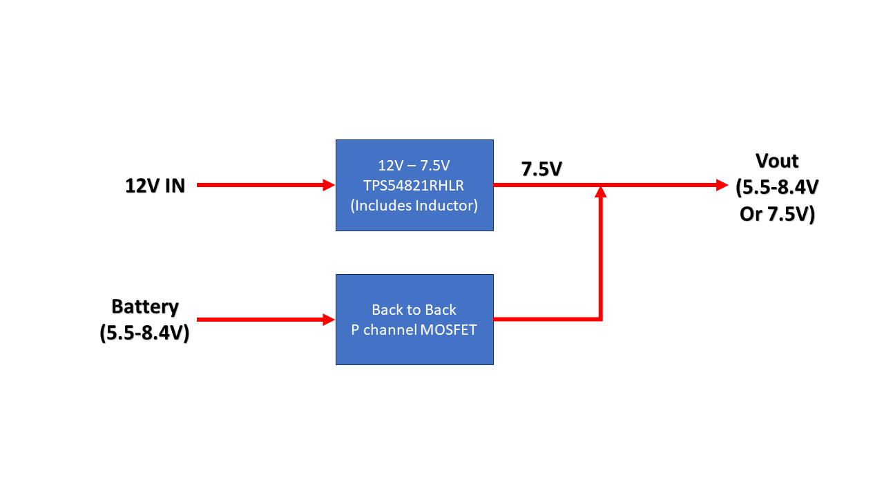
Here are the details of the block diagram
1. The TPS54821 Circuit is designed for 12V Input Voltage and 7.5V Output Voltage
2. The same BUCK output is connected to MOSFETs that is connected to a 2S Lithium Ion Battery
3. We have manual control over the MOSFETs and Enable Pin of the BUCK IC
4. The BUCK IC and MOSFETs are NEVER ON at the same time
5. The MOSFETs are back to back to prevent reverse current flowing from the BUCK to the Battery via the Body Diode if the Battery Voltage falls below 7.5V
5. Are we safe operating the IC in the following conditions.
a. 12V is present, BUCK IC is disabled, back to back MOSFETs are ON and Battery Voltage is connected to the Output of the BUCK IC
b.12V is NOT present, BUCK IC is disabled, back to back MOSFETs are ON and Battery Voltage is connected to the Output of the BUCK IC
6. How does the BUCK IC behave in these instances. These are accidental instances and we will try to avoid these scenarios
a.12V is present, BUCK IC is enabled, back to back MOSFETs are ON, and the Battery Voltage is lower than 7.5V
b.12V is present, BUCK IC is enabled, back to back MOSFETs are ON, and the Battery Voltage is higher than 7.5V
c.12V is NOT present, BUCK IC is enabled, back to back MOSFETs are ON, and the Battery Voltage is lower than 7.5V
d.12V is NOT present, BUCK IC is enabled, back to back MOSFETs are ON, and the Battery Voltage is higher than 7.5V
Thanks,
Deniel
