Other Parts Discussed in Thread: TPS25751, TPS25751EVM
This thread has been locked.
If you have a related question, please click the "Ask a related question" button in the top right corner. The newly created question will be automatically linked to this question.
Hello Sankar,
We do have several resources for using and designing this IC. Here are a few of them:
BQ25756 datasheet
BQ25756 EVM User's Guide
BQ25756 Design Calculator
We also have an FAQ for Reverse Mode.
If you want to combine the BQ25756 with a USB-PD controller, you can check out the TPS25751 and the TPS25751EVM EVM User's Guide has a guide on how to combine the 2 EVMs to test USB-PD contracts.
Let me know if you have any more questions.
Best Regards,
Ethan Galloway
Dear Ethan Galloway,
I hope this message finds you well.
I am currently exploring the Texas Instruments BQ25756 battery charger IC for a project and am seeking information regarding any already tested and working demos or examples. Specifically, I am interested in setups where communication with the BQ25756 is established via I2C from another controller, rather than using BQ Studio.
While I have reviewed the datasheet and related resources such as the BQ25756 EVM User's Guide and Design Calculator, I am keen to understand if there are documented examples or demos that illustrate this specific setup. This information would greatly assist in ensuring a smooth integration of the BQ25756 into our design.
Your guidance on this matter would be highly appreciated. Thank you for your time and assistance.
Best regards,
Sankar Eswaran
Hello Sankar,
Thanks for being patient with this. I will get back to your question on Tuesday. Monday is a federal holiday in the US.
Best Regards,
Ethan Galloway
Dear Ethan Galloway,
I hope this message finds you well.
I am currently working on a project that involves using the Texas Instruments BQ25756 battery charger IC. I am particularly interested in establishing communication with the BQ25756 via I2C from an external microcontroller to send commands, set the registers, and configure the output voltage and current of the charger controller chip.
While I have reviewed the datasheet, BQ25756 EVM User's Guide, and Design Calculator, I am seeking documented examples or demos that illustrate this specific setup. This information would greatly assist in ensuring a smooth integration of the BQ25756 into our design.
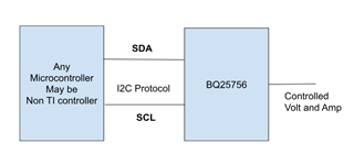
DIAGRAMICAL RESPERSANTATION of My QUESTION:
Your guidance on this matter would be highly appreciated. Thank you for your time and assistance.
Best regards,
Sankar Eswaran
Hello Sankar,
Thanks for working on this with us.
My team doesn't produce any guides on how to interface with microcontrollers. It might be better to ask a question on E2E to the TI microcontroller team. Most microcontrollers will also have a dedicated library to interface over I2C as well.
You probably already know this, but here's a guide on how I2C operates for reference: www.ti.com/.../slva704.pdf
Best Regards,
Ethan Galloway
Hi,
I already installed BQ studio i thought it's communication with BQ25756 so is there available source code of the BQ Studio that will be useful know some more information and what are the features list The BQ52756 charger controller support? And Could you please specify exactly which team I want to ask, and atleast give a link the forum.
Hello Sankar,
Can you clarify your question "what are the features list The BQ52756 charger controller support?"
The forums that may be able to help with an I2C connection for a microcontroller are the ARM-based microcontroller or the C200 microcontrollers forum. You can select these forums when you ask an E2E question.
By the way, here's the driver for real time microcontrollers if that helps: BQ_FREERTOS
Best Regards,
Ethan Galloway
Hi Ethan,
thanks for sharing the project,.
I have some doubts in this project:
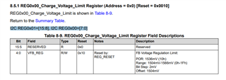
i attached below the BQ25756 Register address,
Actually my doubt is, Charge Voltage Limit register address is 0x00 next address is 0x02 so there is no address called 0x01 am i right ? because the reason i'm saying this is see below:
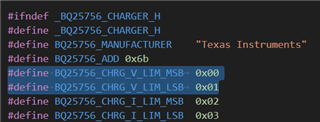
in this project "bq25756_charger.h" , see the below sippet they added the address like charger voltage limit msb - 0x00 and charger voltage limit msb - 0x01
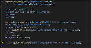
and the below picture the write value msb and lsb charge voltage limit
and my doubt is why split msb and lsb the address of set voltage limit is 0x00 in datasheet but here 0x01 also is in so the reason ?
Hello Sankar,
My understanding is that the Charge Voltage Limit register is a 16 bit register at address 0x00 and also takes up the address space of 0x01 as well. Let me know if that helps.
Best Regards,
Ethan Galloway
ok fine, then i have another doubt,
in the above image, I2C REG0x01=[15:8] ---> this is MSB & address is 0x01 , and I2C REG0x00=[7:0] ---> this is LSB & address is 0x00, but the code you have provided below, mentioned MSB address is 0x00 and LSB address is 0x01 , what's the reason?
Hello Sankar,
It looks like the driver file is written to be big endian. In big endian, the most significant byte (or largest) is stored first and read first.
For the BQ25756, this really doesn't matter though. The only thing that matters is writing the right bits to REG0x01 [4:0] to set the FB voltage.
Best Regards,
Ethan Galloway