This thread has been locked.

If you have a related question, please click the "Ask a related question" button in the top right corner. The newly created question will be automatically linked to this question.

current calibration in BQ20Z95 & OCD recovery

1. In many of board after setting my load current to 2A, then clicking on "CURRENT CALIBRATION", my board start reading wrong value of current. Even if there was no load, it give wrong value of current.

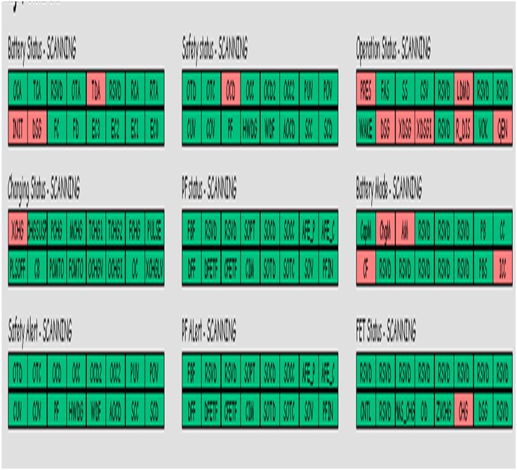
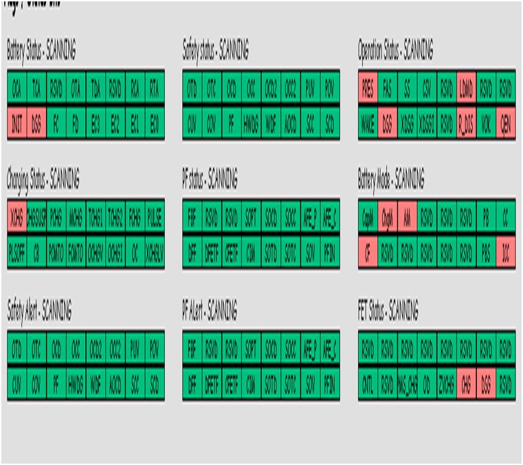
2. I set my external load current greater then "OC 1st Tier dsg", after which [OCD] get set in safety status & DSG fet gets open. Now my load current gets zero & I set my recovery current 200mA. My  DSG fet do not get set. Is this recovery current is +200ma?

  • Before current calibration, following were my Data flash readings:

    After I calibrated current as recommended, my data flash readings changed to following giving a large error


    Please reply at the earliest as this is crucial for my business.

    Deepak Bansal

    Research & Development Engineer


  • Deepak,

    Are you using an EVM or is this part on your own board? If you are using the EVM, make sure you are applying the load current between Pack- and Bat-, not between Pack+ and Pack-. This applies the current directly to the sense resistor, so you should select 'off' for FET control. Apply the 2A load current this way, measure it with a digital multimeter, enter it into the box for 'Enter actual current' and then run current calibration. Then when you take the load away you should be reading a current close to zero. CC Offset and Board calibrations will take care of any additional current that is being falsely reported, but make sure there is no current flowing during those calibrations.

    The way OC Dsg Recovery current works is that the DSG FET is still disabled until the Average Current is below the recovery threshold. The Average Current is a one-minute rolling average of discharge current, so it could be that this average is still above the threshold while you are expecting the FET to come back on. You can also check if there have been any Permanent Flags set on the SBS screen. If there are any, you might need to clear them manually before the DSG FET will turn back on.

    Hope this helps,

    Jason

  • Jason

    Many thanks for your reply.


    You said apply load current between Pack- & Bat-, how to apply current b/w two ground. Do you want to say current b/w PACK- & BAT+. Also ss there any technical document which can help me in better understanding.


    Thanks & Regards

  • Deepak,

    Take a look at the schematic found on page 8 of the bq20z95EVM User's Guide (http://www.ti.com/lit/ug/sluu275/sluu275.pdf). Pack- and Bat- are connected directly to each other with only the sense resistor in between. There isn't an actual ground here, it's just a reference to which voltages are measured against in the rest of the PCB. 

    Hope this helps. Let me know if you need further clarification.

    Regards,

    Jason

  • Jason,

    For current calibration, I used to setup 2A of current by applying load between PACK+ & PACK- & then clicking on CURRENT CALIBRATION BUTTON. But after this there is error as I discussed above in current readings. Is this method correct & if wrong kindly suggest me right method.

    Thanks & Regards

  • Deepak,

    It is the preferred method to apply the load current between Pack- and Bat-, not between Pack+ and Pack-. This applies the current directly to the sense resistor, so you should select 'off' for FET control. The sense resistor is how the gauge measures current, so this method is taking away all the other components in the current path that don't matter for calibration. Apply the 2A load current this way, measure it with a digital multimeter, enter it into the box for 'Enter actual current' and then run current calibration. Then when you take the load away you should be reading a current close to zero. CC Offset and Board Offset calibrations will take care of any additional current that is being falsely reported, but make sure there is no current flowing during those calibrations.

    Regards,

    Jason

  • Jason

    Kindly help me in below issue:

    Run time error "6" - overflow.


     I am using bqEASY to program bq20z95 & above error is generated by entering following values:

    1. No of cells in series - 4

    2. no of cells in parallel  - 15

    3. short circuit protection during charging - 15 AMP

    4. Max steady state discharge current - 20000 mA

    5.Peak short term discharge current -25000 mA

    6. Short circuit detection during discharge- 30A

    Rest of parameters are entered as I had done in my earlier projects & showed no error.I think this is due to large current values.

    Please confirm me if is this error is due to large current values & what is the solution for this. And if this error is due to large current values then what are the threshold values in above case.

  • Deepak,

    What is the capacity of each cell?

    Regards,

    Jason

  • Jason,

    Cap of each cell- 2200mAh

    Thanks & Regards

  • Deepak,

    Are you using the default sense resistor of 10 milliohms? If you are, then it looks like you will be hitting the limit of the Overload voltage threshold register in the AFE (http://focus.ti.com/general/docs/lit/getliterature.tsp?genericPartNumber=bq29330&fileType=pdf). This correlates to the peak short term discharge current you entered. For a 10 milliohm sense resistor, this current max would be 0.205V / 0.01 ohms = 20.5A. You would need to use a smaller sense resistor to get around this limitation.

    Regards,

    Jason

  • Jason,

    I am using two parallel sense resistor of 10mohm each. (Rsns = 5mohm).


    Thanks & Regards

    Deepak Bansal

  • Deepak,

    In that case, your value for short circuit during charge is below the minimum voltage for this register in the AFE. The current that corresponds to the smallest voltage using a 5mohm sense resistor is 0.1V/0.005mohm = 20A.

    Regards,

    Jason

  • Hi Jason,

    As I discussed earlier I have problem in current recovery during discharge.

    I set my OC 1st tier dsg current -> 2000mA

     DSG Current Recovery -> 200ma

    Sense resistor -> 10 mohm


    1. I put load across Pack+ & Pack- & set load current greater than 2A.After this my DSG fet gets open & following was reading of registers:


    2. After that my current reduces to zero because dsg fet gets open, but I kept my load resistor connected to it. After that when avg. current falls below dsg recovery current for more than "Current Recovery Timer", my dsg fet gets back on. As you can see below


    But as told earlier, I kept my load connected to it. Now as you can both chg & dsg fet are on, then current should start again. But it do not get start again & even there is no voltage across PACK+ & PACK-, inspite of fact that both fets are on.

    But if I remove load & reconnect it again, current starts & voltage appears across output. I don't understand why this happens.Kindly help.


    Thanks & Regards

    Deepak Bansal

  • Deepak,

    Can you send me a log file showing this? That would greatly help me to figure out what the issue is.

    Thanks,

    Jason

  • Hi Jason,

    Attached please find find log file.

    During logging, I have checked all the parameters, but some of them don't appear in log file.Please check the same.


    Thanks & Regards

    Deepak Bansal

    bq EVSW Version: 0.9.59 for bq20z95 v1.50	
    Device:950,Ver:1.50
    10/7/2011 5:53:25 PM	
               
    Design Capacity: 4400 mAH
    Design Voltage: 14400 mV
    Specification Info: 0031 hex
    Manufacture Date: 16-Sep-2011 
    Serial number: 0002 
    Manufacturer Name: SealedEn 
    Device Name: SE304 
    Device Chemistry: LION 
    
    Sample	Stamp	~Elapsed(s)	ManufAccess	RemCapAlarm	RemTimeAlarm	BattMode	@Rate(@)	@TimeFull	@TimeEmpty	@RateOK	Temperature	Voltage	Current	AvgCurr	MaxErr	RSOC	ASOC	RemCap	FullChgCap	RunTimeEmpty	AvgTimeEmpty	AvgTimeFull	ChgCurr	ChgVolt	BattStat	CycleCnt	CellV4	CellV3	CellV2	CellV1	FETStatus	SafetyAlert	SafetyStat	PFAlert	PFStat	OpStat	ChgStat
    1	5:53:35 PM	0	0000	440	10	6081	0	65535	65535	0	-37.75	13254	-1447	-344	100	0	0	0	3510	0	0	65535	0	0	0BD0	0	3271	3345	3358	3281	0006	0000	0000	0000	0000	8445	8000
    2	5:53:45 PM	10	0000	440	10	6081	0	65535	65535	0	-37.65	12975	-2642	-1030	100	0	0	0	3510	0	0	65535	0	0	0BD0	0	3436	3427	3440	3427	0004	0000	2000	0000	0000	8475	8000
    3	5:53:55 PM	20	0000	440	10	6081	0	65535	65535	0	-37.75	13725	-4	-454	100	0	0	0	3510	0	0	65535	0	0	0BD0	0	3435	3426	3440	3424	0004	0000	2000	0000	0000	8475	8000
    4	5:54:06 PM	31	0000	440	10	6081	0	65535	65535	0	-37.75	13726	-4	-264	100	0	0	0	3510	0	0	65535	0	0	0BD0	0	3436	3427	3440	3424	0004	0000	2000	0000	0000	8475	8000
    5	5:54:16 PM	41	0000	440	10	6081	0	65535	65535	0	-37.75	13717	-6	-127	100	0	0	0	3510	0	0	65535	0	0	0BD0	0	3433	3424	3437	3422	0006	0000	0000	0000	0000	8445	8000
    6	5:54:26 PM	51	0000	440	10	6081	0	65535	65535	0	-37.75	13716	-5	-62	100	0	0	0	3510	0	0	65535	0	0	0BD0	0	3433	3424	3437	3422	0006	0000	0000	0000	0000	8445	8000
    7	5:54:36 PM	61	0000	440	10	6081	0	65535	65535	0	-37.75	13718	-6	-38	100	0	0	0	3510	0	0	65535	0	0	0BD0	0	3434	3424	3438	3422	0006	0000	0000	0000	0000	8445	8000
    8	5:54:46 PM	71	0000	440	10	6081	0	65535	65535	0	-37.75	13718	-6	-21	100	0	0	0	3510	0	0	65535	0	0	0BD0	0	3433	3424	3438	3422	0006	0000	0000	0000	0000	8445	8000
    9	5:54:56 PM	81	0000	440	10	6081	0	65535	65535	0	-37.75	13717	-6	-13	100	0	0	0	3510	0	0	65535	0	0	0BD0	0	3434	3424	3438	3422	0006	0000	0000	0000	0000	8445	8000
    10	5:55:06 PM	91	0000	440	10	6081	0	65535	65535	0	-37.75	13718	-6	-10	100	0	0	0	3510	0	0	65535	0	0	0BD0	0	3433	3424	3438	3422	0006	0000	0000	0000	0000	8445	8000
    11	5:55:16 PM	101	0000	440	10	6081	0	65535	65535	0	-37.75	13717	-5	-8	100	0	0	0	3510	0	0	65535	0	0	0BD0	0	3433	3424	3437	3422	0006	0000	0000	0000	0000	8445	8000


  • Deepak,

    It looks like Max Error is still set to 100 which happens when there hasn't been a valid learning cycle yet. Have you done this to your pack? Or are you using a supply just for bench testing? What are you using to charge with?

    Regards,

    Jason

  • Hi Jason,

    I am using power supply for testing purpose only.


    Thanks & Regards

    Deepak Bansal

  • Can you measure the gate to source voltage of the FETs to make sure they are really on? Current should flow if the load is connected and the FETs are on.

    Regards,

    Jason

  • Hi Jason,

    When OCD gets set, DSG fet gets off & voltage at gate pin of DSG fet is zero. After Current Recovery Timer, DSG fet gets on in its internal memory(i.e it gets set in SBS data which can be read), but actually in hardware voltage at gate pin is still zero.

    Regret for the delay in response.


    Regards

    Deepak Bansal