This thread has been locked.

If you have a related question, please click the "Ask a related question" button in the top right corner. The newly created question will be automatically linked to this question.

LMR38020: LM38020 as negative power supply

Part Number: LMR38020

Dear,

We must have a negative power supply of -15V.
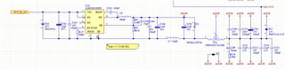
The load is between 250 and 450mA with an input voltage of 24V.
The input voltage can be variering between 20 and 30V.
The switching freq is 400Khz

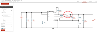
The design is based on the application note snva856b: https://www.ti.com/lit/pdf/snva856

At first can we using the LM38020 as an inverting convertor?
So not, which regulator we can use than?

So, yes
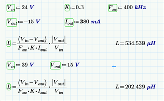
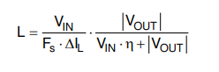
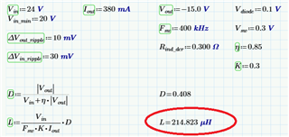
The calculation of the inductor is around the 200µH follow the application note.
If we use this value we will blow up the regulator due to over temperature.
what could be the reason for this?

Only when we reduce the inductance to 56 or 68µH it works better, but the regulator is still quite hot  (70°C).
How we should calculate than the inductor value?

  • Hi GBDH,

    Yes, you can use the LMR38020 as a negative converter. 

    Can you provide the schematic as well as the part numbers of the different inductors you are using?

    Thanks,

    Richard 

  • The only inductor that give the best result is 22µH with a RT of 80K6

    We have try is with different frequencies between 300 and 700Khz with inductors of 33,47,68,82µH.
    Following the formula we should use a inductor of 200µH (see datasheets)
    The inductors we had use are from coilcraft, Bourns and WE.
    Used Series:
    - SRP7050 of Bourns (SRP7050TA-470M, SRP7050TA-680M)
    - WE-PD SMT Power Inductor serie of Wurth: 7447779182,7447714101
    - XAL6060 series coilcraft: XAL6060-333ME_

  • Hi GBDH,

    The inductors look ok to me. 

    For the layout did you connect the thermal pad to the ground plane? That would be the first thing I would check if the part is blowing up due to thermals. Based off of the DS theta j-c, it would seem you are dissipating about 1W of power, which is too much for your application. 

    Thanks,

    Richard 

  • Dear,

    The thermal pad, see EP pin in the schema, is connected to the output and not to the GND. It's a negative power supply.
    Is this correct?

    You say there is a dissipation of 1W, how did you calculate this and how can we solve this so that we have less power loss?
    What is the correct formula we should use for the inverse power supply regarding the inductor value calculation?

     Regards

  • Hi GBDH,

    Yes, that is correct. I phrased the prior comment poorly, I meant that EP should be connected to system ground. Can you check if it is connected to output in the layout? 

    The power dissipation is estimated from the datasheet theta-jc in table 7.4 You mentioned that the measured temperature is around ~70 degree C. Assuming you are operating around room temperature, around 22-23 degree C, you have a difference close to 50 degrees C. The table mentions the theta j-c is about 54 degree C/W, which is close to what you've measured, so I approximated about 1W power dissipation.  

    I did some digging around and it looks like you can implement an IBB using the LMR38020EVM. If possible, I advise modifying the EVM to see if you can generate the expected voltage. Please see the attached link for reference

    Thanks,

    Richard

  • Dear,

    Yes the EP pin is connected to the output on a very large plane

    I think the core problem is how to calculate the inductor.
    On page 20 section 9.2.2.4 in the datasheet we can find the formula for the inductor.
    When we use the equation 10, the result is that we must use an inductor of 202µH for our application


    Even when we use your Webbench power designer tool, we become another inductor value between 56 and 68µH.  (39V used as Vin)
    ps: K = inductor ripple current factor

    Can you please provide us with the correct correct formula for the calculation of the inductor.
    Or if the equation from the datasheet is correct which values we should to use then.

  • Hi GBDH,

    The equation you are using is for a buck converter. In your case since you are using an IBB, you should follow this equation. Other components calculated for the IBB topology are shown here:

    Thanks,

    Richard

  • Dear,

    Sorry i hope that you understand that there is something wrong here.

    Please explain us exactly now why there is so a big different with the inductor coming out of the giving formula and the inductor calculated by the "Web Bench power designer"

    The formula give for the inductor 214µH and the "Web Bench power designer" give an inductor of 39µH  (factor of 5.5 lower)

    If we using the inductor of 220µH on the evaluation kit, it blow up the LMR38020 after 10 sec.
    An inductor of 39µH works better, but the LMR38020 has a to high temperature.

    So explain us now why the "Web Bench power designer" calculate an inductor of 39µH and with the provided formula we having a result of 214µH.


  • Hi GBDH,

    Looks like the webench power designer is calculating based off of the maximum current of the device, which is 2A. You may see further clarification here:

    If you need extra thermal dissipation, you may need to increase the copper heat sink area.

    Thanks,

    Richard 

  • Dear,

    It doesn't look like that the inductor is calculated for a 2A load

    On the WebBench Designer we become the follow inductor values with the same input voltages (20 to 30V) but with various output currents:
    - Iout = 0.38A  inductor of 47µH,  calculated by the formula 98µH
    - Iout = 0.5A    inductor of 47µH,  calculated by the formula 75µH
    - Iout = 1.0A    inductor of 47µH,  calculated by the formula 37µH
    - Iout = 1.5A    inductor of 33µH,  calculated by the formula 25µH
    - Iout = 2A       inductor of  27µH,  calculated by the formula 18µH
    ( first inductor value comes from the Wenbench and the second we had calculated)

    So give us a better explanation of how we must choose the inductor value.

  • Hi GBDH,

    The webench designer is meant for a first-pass design and so there is some limitation to the model.

    I suspect there is possibly some variation due to the inductor ripple factor and variation in the input voltage, which can usually range from 0.2 to 0.4. 

    Based off the above formula you had, for 2A load, 100% efficiency, K = 0.4, VIN = 24V, I get around 28uH, which is close to the Webench value. 

    Thanks,

    Richard