This thread has been locked.

If you have a related question, please click the "Ask a related question" button in the top right corner. The newly created question will be automatically linked to this question.

UCC33420: Abnormal output when isolation side current is over 100mA

Part Number: UCC33420
Other Parts Discussed in Thread: TPS65130, UCC12050, TPS65132

Hi,

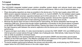
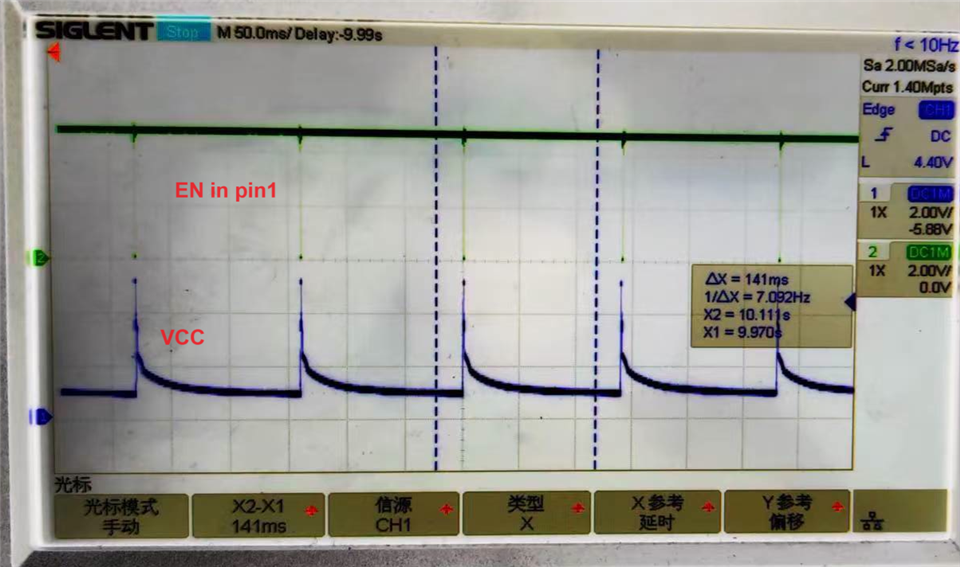
In my new design, we select UCC33420 which can support 300mA (totally 1.5Watts) isolation power, but in my test, the output is prohibited when the output current is over 100mA, please see below plot. in our application the following is DC-DC chip from TI, the total current is ~120mA@5V VCC isolation voltage. please help check it, thanks. 

best regards,

Jay

  • the schematic followed the recommendation in the the d/s, please see above. thanks.

  • btw, If I reduce the load to 80mA, the UCC33420 can work well with 5V output. If I add one resistor 1kohms in the load between 13.5V output from TPS65130's and GNDD, the current is added about 40mA, the UCC33420 is abnormal and output voltage in VCC pin is plotted above. it is restart and protected periodically. 

    best regards,

    Jay

  • Hi Jay,

    -Is this the latest silicon version from UCC33420. When did you get these samples? Where is the VCC_5V signal coming from? Would you please provide the schematic of the pre-regulator (the one providing the VCC_5V)

    -Please, for better debugging, zoom in your waveforms (VINP-GND), (VCC-GND), (EN-GND) ~10us/div. Note that VINP-GND should be also provided.

    Thank you

  • Hi Manuel,

    Thank you for answer. The VCC_5V is from external power supply equipment which can provide 2A@5V. For the waveforms, please see above attached wich have EN-GND and VCC-GND. 

    best regards,

    Jay  

  • Hi Jay,

    -Please provide (VINP-GND), (VCC-GND), (EN-GND) ~10us/div. I would what kind of Fault is triggered on the device.

    -Also, would you please trying disconnecting U10 from the device (open USB5VISO net) and test the UCC33420 itself with a Iload>100mA. Check if the same error happens.

    Thank you

  • The lot is attached as below, thanks

  • Hi Manuel,

    the VCC is referred to GNDS/GNDD or GNDP/GND?

    thanks.

  • VCC is referred to GNDD. VINP and EN TO GND. Sorry for the typo.

    Thank you

  • Hi Manuel,

    Just double confirm if UCC33420 can support 300mA@5V isolated power output?

    We have isolated the FB2, and UCC33420 can work normally. But if we add the load with 33ohms and remove FB2, UCC33420 still can't work.

    thanks.

  • Jay,

    -UCC33420 should be able to deliver 300mA@5V at TA=25C (ambient). When you say "UCC33420 can work normally", what do you exactly mean? What is the difference between FB2 connected and with FB2 disconnected?

    -Please provide the requested waveforms to check the Fault triggered.

    Thank you

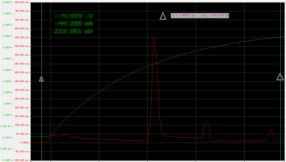
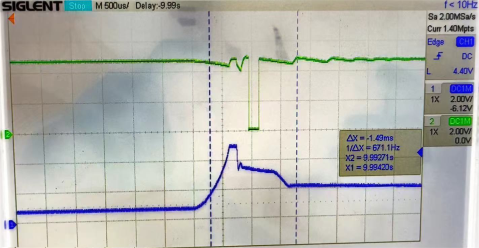
  •  the zoom in is attached, and captured yesterday. due to the ossciloscope limitation, the picture is not very clear. thanks.

  • Yes, we check the d/s and get the UCC33420 can support 300mA@5V output. "the ucc33420 can work normally" means the output voltage is correctly at stable 5V. but once we add the load current to be over 120mA@5V, the UCC33420 VCC output is abnormal, it doesn't matter with if the load is from FB2 or from the paralleled resistor load 33ohms. it sounds the output is prohibited due to internal protection scheme.  

  • Jay,

    Thank you for the info provided. Please provide the requested waveforms without FB2. I need to check what Fault is being triggered. It seems like the device is shutting down (Fault triggered with EN low) and then it is trying to restart unsuccessfully. Please include (VCC5V-GND) with a bandwidth of 250MHz in the scope. Time scale ~10us

    Thank you

  • Thank Mauel.

    Sorry now we can't capture more signals as we had used the replacement solution with UCC12050 compatible solution with high current output (~150mA) from other vendor.

    We need UCC33420 which can give us more margin but unfortunately, it sounds the chip is not strong in our application.  any solution to provide more robust application? thanks.

  • Jay,

    UCC33420 should be able to meet 300mA @5V easily. This is the highest power density DC/DC integrated module you will find in the market. I believe that if we debug this issue, we can solve the problem.

    Thank you

  • Manuel,

    could you please give me the app. notes or checklist to better develop UCC33420 circuit? Any special request for the input signal and the output load? such as surge etc.

    best regards

    Jay 

  • Jay,

    Please follow the layout guidelines of Datasheet. 2.2nF 0402 HF decoupling caps placement is very important for a good efficiency performance and to succeed a good startup sequence. Place 0805 22uF should be connected next to 0402 caps. Place ground planes all over the boards as much as you can for a good Thermal Performance.

    Thank you

  • Thank Manuel,

    It sounds we find out the reason why UCC33240 is restarted periodically, it is the following boost-buck chip TPS65130, it has high transient / surge current during power-on stage as captured current plot. it has over 600mA current which makes UCC33240 close the output. 

    We try many ways but can't reduce this transient current. it sounds UCC33240 solution can't be used in boost/buck supply system. 

    Thanks. 

  • Jay, thanks for this info. It seems like this is a transient event issue. TPS device overloads UCC33420 when turning it on and USB_5VISO (output of UCC33420) goes low and try to restart unsuccessfully due to the TPS device continuous inrush current. Please, follow up with my recommendations below:

    1.Bypass UCC33420 and connect 5V power supply directly to input of TPS device and measure input current. This will help us to verify the 600mA peak inrush currents needed for TPS device to startup. See picture below for better understanding on where to connect power supply.

    2. Please, show value of output capacitance of TPS65130 in the schematic.

    3. Please, share full schematic (showing full output side of TPS65130) and layout of UCC33420+TPA65130. I will review it.

    4. It is very important in the layout the placement of the input and output caps of UCC33420 for a good startup sequence. Please follow the guidelines showed above and review it in your layout.

    5. Lets try increasing the output capacitor of TPS device for a lower inrush current.

    Number 5 should be at the end after we verify number 1 and reviewing the layout. I believe that with these steps we can solve the issue.

    Thank you

  • Thank Manual. 

    Actually the above inrush current plot is captured when 5V supply is infected into TPS65130 input directly and UCC33420 is removed. that is to say No.1 is done.

    We had tried different load and capcitors in the TPS65130 output pins but inrush current always is very high. When I check TPS65132 which has startup inrush current spec. and plot, this inrush current also is high. what we can do is to increase the soft start time to reduce the transient current.

    Thank you.

  • Manuel

    Just want to check, ucc33420 internal UVLOP is triggered when output voltage dropped to 90% from a higher voltage, then the FLT is triggered and the iso output is disabled? 

    The inrush current or dropped voltage pulse is ~100us level, can we filter out this and make the protection scheme more robust? Just like many isolation device used in noisy condition, filter is required to improve noise immunity. 

  • Jay,

    -UCC33420 is triggering UVP fault after the 600mA overload current and then is trying to restart after 160ms unsuccessfully.

    -Thank you for the test with the TPS device connected to the power supply. Please, follow the following:

    -Share the layout of UCC33420+TPS65130 to be reviewed.

    -You mentioned you try increasing output capacitance of TPS device. What was the initial value and to what value did you increase it?

    -Try increasing Cout of UCC33420. It is 2.2nF+22uF now. Try increasing a 10uF extra cap. Add this cap right after the 22uF. You can remove the solder mask in your layout and connect it next to it. As mentioned above, the cap placement is very important for a good startup sequence.

    Thank you