This thread has been locked.

If you have a related question, please click the "Ask a related question" button in the top right corner. The newly created question will be automatically linked to this question.

BQ40Z50-R2: BQ40Z50-R2: Low charge current

Part Number: BQ40Z50-R2
Other Parts Discussed in Thread: BQSTUDIO, , BQ40Z50, EV2400

Hi,

When trying to charge my battery pack i realised that it was not charging properly 

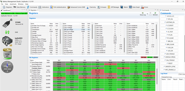
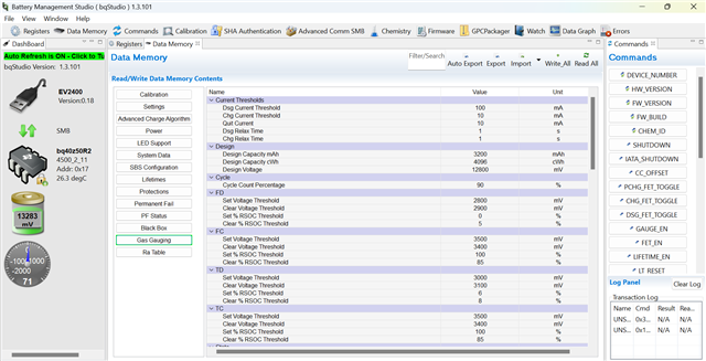
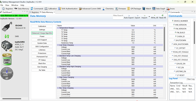
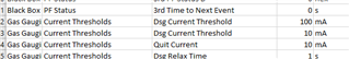
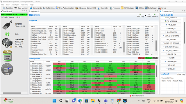
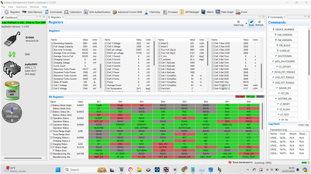
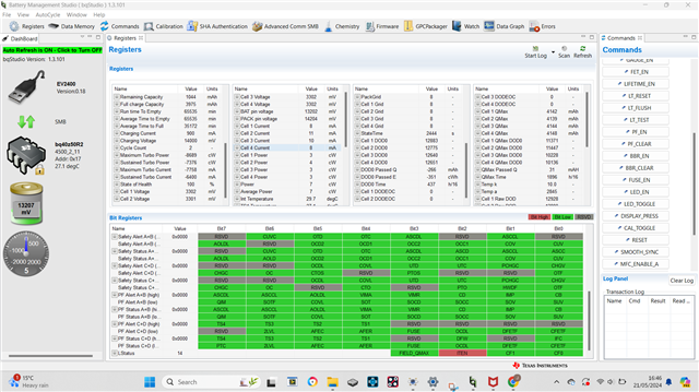
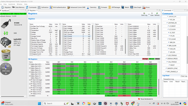
after observing battery in BQstudio i noticed that the charge current was <10mA 

what could be the potential cause here ?

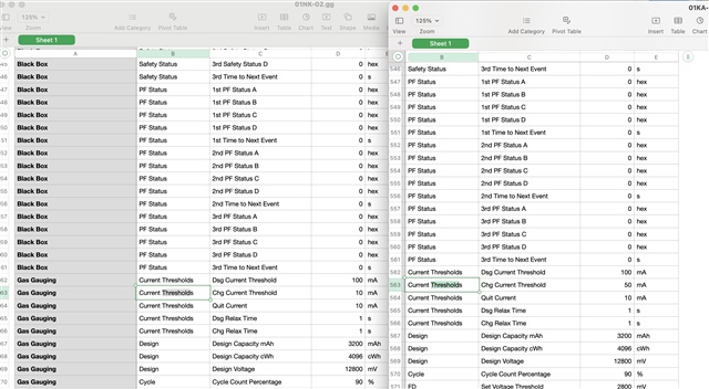
i've attached BQstudio screenshot showing pack settings

Regards

Jonathan Kabangu

  • Hi Jonathan,

    At the top of the Bit Register section of the screenshot, can you please ensure that the FETs are being enabled (using the FET_EN command) and that the gauge is in Charge Mode?

    Can you also please confirm that the charge current being passed is greater than the Charge Current Threshold?

    Regards,

    Anthony Baldino

  • Hi Anthony,

    Sorry for the late response,

     Here's the response:

    1. Is there another way of identifying "charge mode" apart from looking at the charge current fuel gauge & the current/average current register ?
    2. The FET is enabled cause the Flag is RED correct?
    3. What's the definition of "charge current threshold "??,this value is 50mA

    I've also attached the Logs:

    A.log

    Let me know if you find anything interesting which can lead to the issue being seen

    Regards

    Jonathan Kabangu

  • Hi Jonathan,

    1. When charging has begun, the DSG bit that is seen red above should be cleared and turn green.

    2. Yes, FET_EN being red does indicate that it is enabled.

    3. Charge Current Threshold is the minimum current threshold needed for the gauge to enter charging mode. With the values above, the gauge will need to see a current greater then 50mA for at least 1s to enter charge mode. This current is measured by the sense resistor attached to SRN and SRP.

    Can you please tell me more about how charging is being attempted such as how much current is being put on the pack connection?

    Regards,

    Anthony Baldino

  • Hi Anthony,

    1.on that screenshot the charge current is about 7mA and the “DSG” bit is not turning Green Ofcourse you’ve explained this ,as this is below the min charging threshold of 50mA 

    2.what does it mean if the “FET_EN” is enabled but the pack is not charging ?

    3.our pack is seeing no more than 30mA ,so definitely below charge current threshold!!!

    **Our pack receives charge by two ways** ,

    • first way is charge input via USB-C connector 
    • second way is by applying power directly to Pack+ and pack-

    Here's schematic for your reference:

    Regards

    Jonathan Kabangu

  • Hi Anthony,

    Any update on the questions above

    Regards

    Jonathan Kabangu

  • Hi Jonathan,

    2.what does it mean if the “FET_EN” is enabled but the pack is not charging ?

    3.our pack is seeing no more than 30mA ,so definitely below charge current threshold!!!

    Enabling FET_EN allows the gauge to control the CHG FET and DSG FET based on the current being read from the sense resistor. If FET_EN is enabled and the read current is greater then the Chg Current Threshold, then Charge Mode will be entered.

    If the pack is seeing no more then 30mA, then you can reduce the Chg Current Threshold to allow it to enter charge mode.

    Regards,

    Anthony Baldino

  • Hi Anthony,

    1.where can I find a document that explains each of the bit Registers flag such as GAUGE_EN,LED_EN,PF_EN,FET_EN etc…

    a document that can explain each function and how to control them 

    2.how do I change the minimum charge current threshold value settings, do I need manufacturing access?

    Regards

    Jonathan Kabangu

  • Hi Jonathan,

    The bq40z50-R2 TRM has the necessary information on the bit register flags and how to control them:

    https://www.ti.com/lit/pdf/sluubk0 

    2. Changing the Charge Current Threshold can be done by finding its parameter in Data Memory and clicking the value, which should allow it to be altered, and changing it. Please ensure that it is written back to the gauge and the gauge is unsealed when this is being attempted.

    Regards,

    Anthony Baldino

  • “Changing the Charge Current Threshold can be done by finding its parameter in Data Memory and clicking the value, which should allow it to be altered, and changing it. Please ensure that it is written back to the gauge and the gauge is unsealed when this is being attempted.“

    1.how do I ensure it’s written to the gauge ? How do I confirm this change is applied?

    2.i have both “unsealed” and “unsealed for full access “ access ,which one of the two will enable me to make the change and write it to the gauge ?

    Regards

    Jonathan Kabangu 

  • Hi Jonathan,

    1. An easy way to check after pressing Write All, is to press Read All to make sure the same value is read out. You can also check by power cycling the gauge and ensuring the same changes have been made.

    2. I would use Unsealed Full Access for this.

    Regards,

    Anthony Baldino

  • Hi Anthony,

    when you say the “Gauge” are you referring to the BQ40Z50 IC inside the pack ,the EV2400 module or something else ?

    Regards 

    Jonathan Kabangu 

  • Hi Jonathan,

    I am referring to the bq40z50 IC itself to be power cycled.

    Regards,

    Anthony Baldino

  • Hi Anthony,

    one more question:

    How does one power cycle the bq40z50 IC as it's inside as part of our pack ?

  • Hi Jonathan,

    If a power cycle is not possible, then I believe sending the RESET command for this device should suffice in representing the changes to the data memory.

    Regards,

    Anthony Baldino

  • Hi Anthony,

    The RESET command just Reboots the pack essentially?

    it does not erase or remove any preceding data?

    Regards

    Jonathan Kabangu

  • Hi Jonathan,

    RESET will restart the gauge with the settings written to the Data Flash still on it, so if they are not written correctly they will not be represented after RESET. However, it is not a factory reset and should still have all the same settings on it.

    Regards,

    Anthony Baldino

  • Hi Anthony,

    When setting charge algorithm/logic for our pack ,cause this pack is part of a bigger system, it receives charge Via input USB-C port that get it's power from OBD cable ,i'll show pics below:

    is there any recommendation/advice around :

    1. Trickle charging (topping up charge at above 95%)
    2. multiple Charge cycles at high RSOC(95%~100%),can this affect the capacity/capacity retention rate???
    3. when our pack goes from 0%~100% should we wait for the pack to fall at a specific RSOC before Enabling Charge FET's to charge again?
    4. Since Vehicle battery is not constant DC and it can go up and down ,what's the issue here, e.g for our system we enable charge at 12.4V, if the vehicle is constantly fluctuating between 12.4V~12.3V every few second what's the long term impact or issue here, think of it from a pack(cells) perspective it's seeing pulses of charge current every few seconds)
    5. Batteries charge with CC/CV mode with our vehicle battery Fluctuating around 12.3V~12.4V and turning ON/OFF every 60s(to check voltage level is above 12.4V so we don't drain vehicle batteries)  does this go against the nature of CC charging?

    i'll attach a snapshot of how a typical device on the field behaves:

    Regards

    Jonathan Kabangu

  • Hi Jonathan,

    • Trickle charging (topping up charge at above 95%)
    • multiple Charge cycles at high RSOC(95%~100%),can this affect the capacity/capacity retention rate???
    • when our pack goes from 0%~100% should we wait for the pack to fall at a specific RSOC before Enabling Charge FET's to charge again?

    I believe the most important thing regarding the constant charging depicted above is allowing the gauge to enter a relax state (with no charge or current being applied) for OCV measurements to be made. If you are constantly charging over a significant amount of time and this relax is ignored, then there could be issues with the calculations conducted by the gauge.

    • Since Vehicle battery is not constant DC and it can go up and down ,what's the issue here, e.g for our system we enable charge at 12.4V, if the vehicle is constantly fluctuating between 12.4V~12.3V every few second what's the long term impact or issue here, think of it from a pack(cells) perspective it's seeing pulses of charge current every few seconds)
    • Batteries charge with CC/CV mode with our vehicle battery Fluctuating around 12.3V~12.4V and turning ON/OFF every 60s(to check voltage level is above 12.4V so we don't drain vehicle batteries)  does this go against the nature of CC charging?

    Regarding this, how long are the pulses of current being applied and what is the current value? This would give us a better idea of how to go about this.

    Regards,

    Anthony Baldino

  • Hi Anthony,

    • So once our Pack reaches 100% RSOC ,it does not charge again till it drops below 95%(This is based on our Charge FET release setting of 95%)                                                                                                       This period when the Pack goes from 100% down to 95% the pack enters discharge mode so it does not enter relax mode ,correct?                                                                                                                                                                                                                                                                                                                   cause according to the document relax is entered when either "Current goes below Quit current for a period of chg relax time for Charge mode" or  when "current goes above  (-)quit current for a period of dsg relax time
    • So is it true to say that relax mode is entered properly only when the Pack is not charging or discharging whilst the pack is at REST ,the data below from the document kind of confirms it??

    • Our device is always housed inside the unit thus meaning that it's always discharging to the system ,when a voltage of >12.4V is seen then it begins charging,does this mean that our system never enters relax then?

    2.

    • once our system sees >12.4V ,it enables charging for 1 minute(60s) at a current of about 800mA-1000mA, once 60s is reached then the algorithm turns off charging for about 1s to observe that voltage is still >12.4V then charging begins again

    Regards

    Jonathan Kabangu

  • Hi Jonathan,

    • So once our Pack reaches 100% RSOC ,it does not charge again till it drops below 95%(This is based on our Charge FET release setting of 95%)                                                                                                       This period when the Pack goes from 100% down to 95% the pack enters discharge mode so it does not enter relax mode ,correct?                                                                                                                                                                                                                                                                                                                   cause according to the document relax is entered when either "Current goes below Quit current for a period of chg relax time for Charge mode" or  when "current goes above  (-)quit current for a period of dsg relax time
    • So is it true to say that relax mode is entered properly only when the Pack is not charging or discharging whilst the pack is at REST ,the data below from the document kind of confirms it??

    Your understanding is correct, the current must be below the quit current for the gauge to enter relax mode. However, the gauge needs to clear the dV/dt condition when entering relax before calculations are made, where the resting voltage of the cell must not change by more then 4uV per second. That will determine when the gauge is truly in relax and making calculations.

    Our device is always housed inside the unit thus meaning that it's always discharging to the system ,when a voltage of >12.4V is seen then it begins charging,does this mean that our system never enters relax then?

    Yes, if there is always a current being applied to the cell, the gauge will never enter relax. This can cause issues since it will not allow for the necessary calculations to be made.

    Regards,

    Anthony Baldino

  • Hi Anthony,

    1.Yes, if there is always a current being applied to the cell, the gauge will never enter relax. This can cause issues since it will not allow for the necessary calculations to be made.

    JK:if these batteries need quit current of <10mA in charge or discharge to enter relax, how can we ever achieve this if our charge current is above 800mA in charge or -200mA in discharge in operation?

    2.

    This is photos of me altering the charge current to <10mA, as per your definition this is the minimum charge current that needs to be seen for the gauge to enable charging, even after doing this as you can charge current was <100mA, not sure why

    Regards

    Jonathan Kabangu

  • Hi Jonathan,

    JK:if these batteries need quit current of <10mA in charge or discharge to enter relax, how can we ever achieve this if our charge current is above 800mA in charge or -200mA in discharge in operation?

    Even if the thresholds are changed to allow the gauge to enter relax at a higher current, the cell will never truly enter relax until the dV/dt condition is cleared, which will not clear until there is a minimal to no current being applied to the gauge. Is there no way in this application that a rest period can be applied?

    This is photos of me altering the charge current to <10mA, as per your definition this is the minimum charge current that needs to be seen for the gauge to enable charging, even after doing this as you can charge current was <100mA, not sure why

    I would not recommend changing the charge current to under 10mA since this will not change the performance of the gauge since the present charging current is 800mA. However, if the value cannot be changed, can you please tell me more about how you are going about altering this value?

    Regards,

    Anthony Baldino

  • Hi Anthony,

    1.Even if the thresholds are changed to allow the gauge to enter relax at a higher current, the cell will never truly enter relax until the dV/dt condition is cleared, which will not clear until there is a minimal to no current being applied to the gauge. Is there no way in this application that a rest period can be applied?

    JK: when you say "the dV/dt condition needs to be cleared" since this value is 4uV/s ,so the gauge will monitor for this value then if seen we then enter relax, in other words it will be CLEARED once that value is seen when pack is at rest(no current is being applied or pulled from cells)?

    JK:i'm not sure if we're ever at a rest state, cause think of it ,to be at rest no current should be applied by charging or discharging, at no point in this application the battery is at rest cause the pack lives inside Hub/device meaning it's always discharging(pulling current) and charging when charging condition are met

    JK:to achieve rest for our device the pack has to be removed hub once every while to allow no charge or discharge activity, from your experience how should we resolve this issue? Slight smile

    2.I would not recommend changing the charge current to under 10mA since this will not change the performance of the gauge since the present charging current is 800mA. However, if the value cannot be changed, can you please tell me more about how you are going about altering this value?

    JK:sorry for the confusion what i meant is i changed the charge current threshold to <10mA as it was suggested by you earlier since our pack was not charging and seeing mostly current below <10mA when charge input connection was applied,

    • please see video showing the no charge issue with the pack

    • Please see video showing charging issue with this Specific Pack Versus a pack that works properly

    Regards

    Jonathan Kabangu

  • Hi Jonathan,

    in other words it will be CLEARED once that value is seen when pack is at rest(no current is being applied or pulled from cells)?

    Yes, ideally there would be no current however I believe this can be achieved with a slight current as long as it does not change the voltage of the cell by 4uV/s.

    to achieve rest for our device the pack has to be removed hub once every while to allow no charge or discharge activity, from your experience how should we resolve this issue?

    This is a difficult issue since the gauge is very reliant on the calculations and measurements taken during the relax period. I believe the document below could potentially offer some insight of how to go about this:

    https://www.ti.com/lit/pdf/slua997 

    For each of the two packs (functioning and non functioning), is it possible to send the .gg file of both so I can take a look to see what might be holding the charge up?

    Regards,

    Anthony Baldino

  • HI Anthony,

    • A solution we came up with was to apply a low power mode ,let's say 25% RSOC (Above min RSOC for balancing),in this mode we can disable charging and reduce system power consumption to be below the quit current region(10mA),this will allow our Pack to enter relax mode since it won't charge and discharge current will be below 10mA, if dv/dt is all good ,OCV is good and min delta between cells then balancing,RSOC,FCC etc.. calculation can take place

    how does that sound ?

    • Sure ,I'll attach the GG file for the two packs 
    1. Faulty(no charging) pack GG:01NK-02.gg.csv                                                                                                            
    2. Good Pack GG:01KA-02.gg.csv

    Let me know if you find anything interesting between the two that may indicate why faulty pack 01NK-02 is not charging

    Regards

    Jonathan Kabangu

  • Hi Jonathan,

    • A solution we came up with was to apply a low power mode ,let's say 25% RSOC (Above min RSOC for balancing),in this mode we can disable charging and reduce system power consumption to be below the quit current region(10mA),this will allow our Pack to enter relax mode since it won't charge and discharge current will be below 10mA, if dv/dt is all good ,OCV is good and min delta between cells then balancing,RSOC,FCC etc.. calculation can take place

    how does that sound ?

    I believe this could work as long as there is enough time in the low power state to allow for the OCV measurements to take place.

    Regarding the non-functioning pack, I found something odd in the .gg file where there are two DSG Current Thresholds and no CHG Current Threshold:

    Was there any alterations done to this .gg file before being sent or was this how it was pulled?

    Regards,

    Anthony Baldino

  • Hi Anthony,

    1.is there an average time for all this to be completed: OCV, dv/dt, Cell balancing,FCC RSOC calculation update, what's the minimum rest time the pack needs to get efficient performance for our pack 

    cause we are planning to tell customers in the field to let their pack go to rest when the device is not in operation, we just need some suggestion around the minimum rest time

    2.i did alteration as you told me to change the original 50mA to something less like 10mA

    funny enough the settings looks normal on my side

    see screenshot:

    not sure what's happening here?

    Regards

    Jonathan Kabangu

  • Hi Jonathan,

    1.is there an average time for all this to be completed: OCV, dv/dt, Cell balancing,FCC RSOC calculation update, what's the minimum rest time the pack needs to get efficient performance for our pack 

    cause we are planning to tell customers in the field to let their pack go to rest when the device is not in operation, we just need some suggestion around the minimum rest time

    Typically, we recommend two hours of the gauge being at rest for the entire process. It usually takes about 30 minutes for the dV/dt condition to be cleared since the voltage needs to relax after the charge or discharge has been completed.

    2.i did alteration as you told me to change the original 50mA to something less like 10mA

    funny enough the settings looks normal on my side

    see screenshot:

    Just to confirm, this was pulled from the faulty pack correct? If this has been corrected now, can you please send us a new .gg file so we can look through it again?

    Regards,

    Anthony Baldino

  • Hi Anthony,

    1.Typically, we recommend two hours of the gauge being at rest for the entire process. It usually takes about 30 minutes for the dV/dt condition to be cleared since the voltage needs to relax after the charge or discharge has been completed.

    JK: is 30 minutes enough to get the balancing process for the cells at least?

    2.Just to confirm, this was pulled from the faulty pack correct? If this has been corrected now, can you please send us a new .gg file so we can look through it again?

    01KA-02:2450.01KA-02.gg.csv

    (faulty Pack)01NK-02:2450.01NK-02.gg.csv

    Here's a picture showing each pack's gg file side by side and it does not show the 2 chg threshold:

    please check again and update me on your findings

    Regards

    Jonathan Kabangu

  • Hello Jonathan,

    Anthony will be out town for a while, but I can continue to support you.

    I checked the gg file and see that Chg current Threshold was changed to 10mA for the 01NK-02 gg file. Now I would also recommend changing the Quit Current Threshold value to something smaller than 10mA since Quit Current Threshold needs to be less than Chg Current Threshold. Quit Current Threshold can be set to 5mA. 

    Cell balancing takes a while to fully finish. I can not give a definite answer on how long cell balancing will take since that depends on many factors like battery chemistry and the amount of imbalance between the cells. However, the gauge does report out how long cell balancing is predicted to take.

    Regards,

    Nick Richards

  • Hi Nick,

    "However, the gauge does report out how long cell balancing is predicted to take."

    JK:What's the setting to check the gauge's predicted cell balancing duration?

    Regards

    Jonathan Kabangu

  • Hi Jonathan,

    That time is reported in the Cell "X" Bal Time register.

    Regards,

    Nick Richards

  • Hi Nick/Anthony,

    Few questions here:

    1. i was told balancing only occurs if Pack enters relax mode ?,my question is what will happen if we enter relax/rest mode then we apply charge current to Pack?
    2. I say this because i'm seeing balancing CB & REST during charge is this normal??

    If you look at the screenshot above you'll see the Pack charging at the same time the REST & CB  flag is also raised, is this a normal occurrence or is this bad for the battery?

    Regards

    Jonathan Kabangu

  • Hi Jonathan,

    i was told balancing only occurs if Pack enters relax mode ?,my question is what will happen if we enter relax/rest mode then we apply charge current to Pack?

    Cell balancing can occur if the gauge is in relax or charging, however the gauge needs to be in relax to calculate the necessary values for cell balancing:

    If you apply a charge current to the pack while in relax mode, the gauge will leave relax mode and enter charge mode.

    I say this because i'm seeing balancing CB & REST during charge is this normal??

    How long has a charge current been applied to the cell? CB is ok to be set here but REST should be cleared eventually after some time of the charge current being applied.

    Regards,

    Anthony Baldino

  • Hi Anthony,

    "Cell balancing can occur if the gauge is in relax or charging, however the gauge needs to be in relax to calculate the necessary values for cell balancing"

    • i've seen from my testing today that balancing does occur during charging ,or at rest but it's disabled during DISCHARGE,is this true ?
    • one thing i realised is Pack's are not entering REST when quit current is 10mA @1s,should i be concerned ,e.g when i reach RSOC 100% and when quit current is 10mA @1s it's not setting the REST bit immediately ,is there other conditions that we're missing to enable this,see screenshot :charge current is at 0A so why is my pack not entering REST

    Regards

    Jonathan Kabangu

  • Hi Jonathan,

    i've seen from my testing today that balancing does occur during charging ,or at rest but it's disabled during DISCHARGE,is this true ?

    Correct.

    one thing i realised is Pack's are not entering REST when quit current is 10mA @1s,should i be concerned ,e.g when i reach RSOC 100% and when quit current is 10mA @1s it's not setting the REST bit immediately ,is there other conditions that we're missing to enable this,see screenshot :charge current is at 0A so why is my pack not entering REST

    The REST bit will become high after the gauge has had enough time to relax and meet the 4uV/s condition, which will usually occur after 30 minutes. In the screenshot above, if you went from charge mode to relax, then this is correct, due to the CHG bit in Operation Status being cleared, and the DSG bit becoming set. In our gauges, the DSG bit becoming set reflects that the gauge is in Discharge or Relax mode. 

    Regards,

    Anthony Baldino

  • Hi Anthony,

    "The REST bit will become high after the gauge has had enough time to relax and meet the 4uV/s condition, which will usually occur after 30 minutes. In the screenshot above, if you went from charge mode to relax, then this is correct, due to the CHG bit in Operation Status being cleared, and the DSG bit becoming set. In our gauges, the DSG bit becoming set reflects that the gauge is in Discharge or Relax mode. "

    • if DSG bit reflects that the gauge is in discharge/REST then the pack will never balance since CB only occurs in charge/Relax?
    • Discharging is when DSG bit is set when current is -(negative)
    • and Relax mode is when DSG bit is set when current is showing 0mA?

    Regards

    Jonathan Kabangu

  • Hi Jonathan,

    if DSG bit reflects that the gauge is in discharge/REST then the pack will never balance since CB only occurs in charge/Relax?

    For clarification, Relax and Rest are essentially the same thing, only difference being whether the gauge has cleared the 4uV/s condition. Relax is a mode, when REST is a bit that is cleared during rest when the condition has been met. The REST bit will only be set when the gauge is in relax mode.

    DSG being set means the gauge is either in discharge or relax. The gauge will able to complete cell balancing if the gauge is in relax mode, with the REST bit set.

    Discharging is when DSG bit is set when current is -(negative)

    Discharge mode is when the current being measured by the gauge is greater then the Discharge Current Threshold. 

    and Relax mode is when DSG bit is set when current is showing 0mA?

    Relax mode is when the current measured by the gauge is less than the Quit Current for at least CHG Relax Time or DSG Relax Time, depending on which mode the gauge is in before entering relax. 

    Regards,

    Anthony Baldino

  • Hi Anthony,

    "For clarification, Relax and Rest are essentially the same thing, only difference being whether the gauge has cleared the 4uV/s condition. Relax is a mode, when REST is a bit that is cleared during rest when the condition has been met. The REST bit will only be set when the gauge is in relax mode"

    • relax is the mode the pack enters once quit current is met once charging or discharging is removed?
    • in the above comments you mentioned we enter relax after 30 minutes?, the documentation says:

    A relaxed state is achieved if the battery voltage has a dV/dt of < 4 μV/s. Typically, it

    takes 2 hours in a charged state and 5 hours in a discharged state to ensure that the dV/dt condition is

    satisfied. If 5 hours is exceeded, a reading is taken even if the dV/dt condition was not satisfied. The

    GaugingStatus()[REST] flag is set when a valid OCV reading occurs.

    • so does this mean we possibly have to wait 5 hours (from discharge). or 2 (from charge) to start balancing?

    • Is CB & CB_EN only TRUE when REST bits is set?

    Regards

    Jonathan Kabangu

  • Hi Jonathan,

    so does this mean we possibly have to wait 5 hours (from discharge). or 2 (from charge) to start balancing?

    We typically recommend that the entirety of the rest period be 5 hours after discharge and 2 hours after charge. The gauge should clear the dV/dt condition within the first 30 minutes of this time. For the remaining period of it, it will continuously take calculations, where typically the most accurate calculations are taken near the end of this time due to the cell being at its most relaxed point. The gauge should begin balancing after the initial measurements and calculations are made.

    • CB & CB_EN only TRUE when REST bits is set?

    Below are the situations where CB is set:

    I believe that CB_EN should set during charging and when the rest bit is set.

    Regards,

    Anthony Baldino

  • Hi Anthony,

    Thanks for the solution on this topic

    it's been very insightful

    Regards

    Jonathan Kabangu