This thread has been locked.

If you have a related question, please click the "Ask a related question" button in the top right corner. The newly created question will be automatically linked to this question.

TPS65131EVM-839: VNEG unstable with varying load

Part Number: TPS65131EVM-839

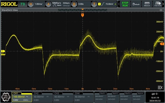
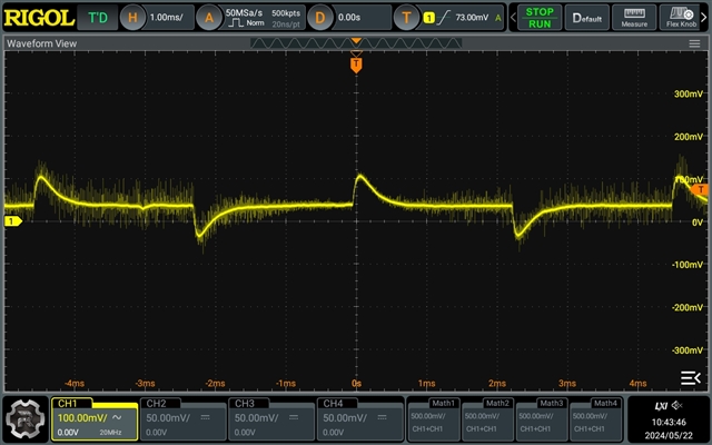
Using the TPS65131EVM-839 board, I find the negative output is unstable with varying load. Using a programmable load, stepping between 10ma and 50ma with 4ms period, I observe the output voltage oscillate. I've attached a screenshot, but what is not clear from this static image is that the "sine" looking portion of the waveform is varying with time from cycle to cycle. I first observed this in my application, where this regulator is powering a number of opamps. Driving those opamps near rail-to-rail with a 1kHz signal causes VNEG to oscillate at the same 1kHz rate.

VPOS is better behaved, although I see slight oscillations--observe the "pip" at 3ms in the VPOS screenshot I've attached. Again, this is varying with time, but this is not clear from a static image.

Since the common cause for these type of issues is layout, I've tried this same experiment with the EVM board, with similar results. So, unless the EVM layout is also suspect, this is probably not a layout issue.

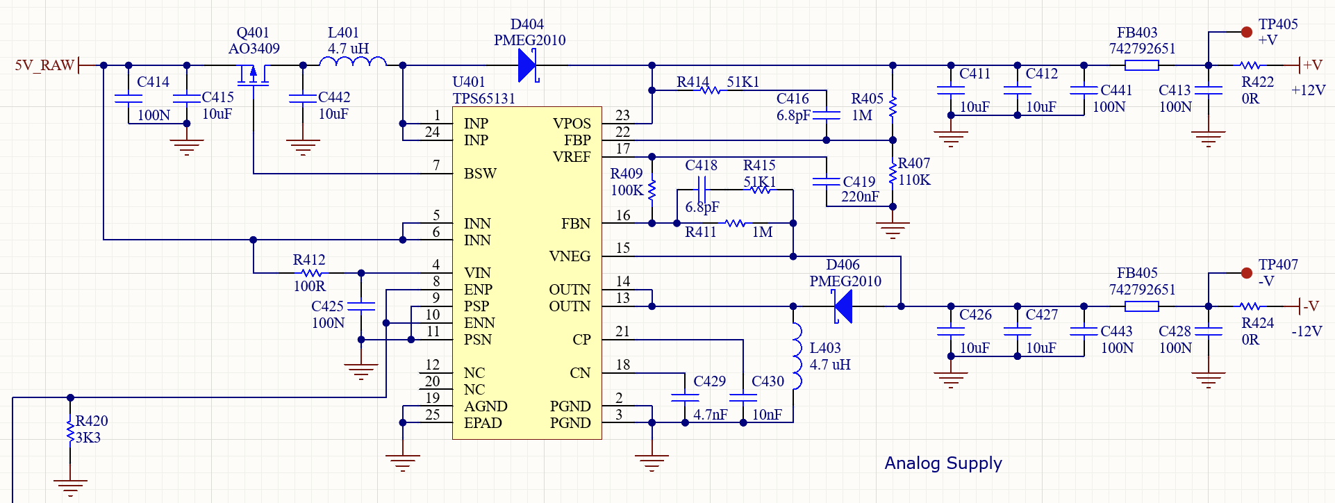
The only change I have made to the EVM is to change the output voltage to +/-12V by changing R3 to 1M, R2 to 110K, and R5 to 1M.

Should I be able to get a non-oscillating output with varying load?

  • Hi Paul,

    Could you please send me the schematic for double check? You can send it to me through private message if you have confidential concern.

    BR

    Patrick

  • I'll attach my schematic below, but I think you may not have read my post throughly. I am observing this behaviour with the EVM board, and that hardware is what is creating the screenshots above. So, while my design also does this, the problem exists on the EVM and thus is not related to my schematic or layout.

    Does this make sense?

  • Hi Paul,

    I misunderstood before. For this oscillation, it is actually the behavior of load transient. This will be related to the loop response of the converter. You can adjust the C418 to optimize the load transient performance. And larger output capacitance will also have improvement.

    BR

    Patrick

  • Hi Patrick,

    I had previously tried adjusting C418--15pf and 33pf (convenient values I had in hand) to see what effect this might have, but with little improvement. Do you have some guidance here?

    Also, I've observed problems with larger load capacitance--the switcher will not start with capacitances > ~47uF. In other designs, not using this part, I might otherwise use a much larger value--470uF or 1000uF, but that doesn't seem possible here. Is there a workaround for this?

    Paul

  • Hi Paul,

    Could you please let me know what is your acceptable peak current during load transient?

    BR

    Patrick