A related question is a question created from another question. When the related question is created, it will be automatically linked to the original question.
If you have a related question, please click the "Ask a related question" button in the top right corner. The newly created question will be automatically linked to this question.
Ideally i used 4.3ohm resistance in USB lines, anyway i will use Cio capacitance also.
Additionally, in datasheet i saw the insertion loss is -3dB near 800MHz, i hope this large loss chances of degrade the eye diagram, when using USB cable (roughly 1.6m). Is there anyway to improve the performance of eye diagram or any other TI parts recommended with lesser insertion loss?
USB cables create an equivalent capacitance and resistance making the USB port bandwidth more narrow and impede the signal integrity. So signal integrity will become worse with longer cables.
The eye diagram pattern should be measured first to be used as reference when selecting the LC values. To improve the the eye opening, a series inductor between 5nH to 15nH should be added first and tuned to extend the bandwidth at the expense of less linearity. Then add and tune a shunt capacitor to compensate the inductor and improve the linearity. 4.7pF is a good value to start with.
In datasheet, the insertion loss mentioned as -3dB near 800MHz. How to include this data transmission loss in Simulation. Since i considered only RDS_ON value only.
How the insertion loss plot derived? Can you share more information about this.
Unfortunately, I won't be able to help when it comes to generating a Spice model for this device.
I believe a network analyzer was used to measure the insertion loss. I will see if I can reproduce the same measurement for DP and DM, and if successful, I will try to generate an SxP file to be used for simulation. However, it may take up to about a week before I can deliver this. Will two S2P files (one for DP and one for DM) or an S4P file work for you?
In the datasheet, the data transmission loss of -3dB measured @800MHz. In this measurement regards, can you clarify below queries.
At what electrical condition & mode of operation, the data transmission measured?
If the measurement is for ideal IC operating condition means, -3dB loss more & we cant able to achieve proper eye diagram as per USB standard. In this condition, -3dB is valid or how much of IC loss we should consider for simulation?
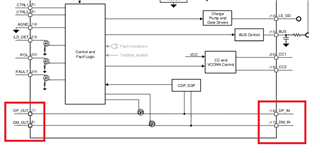
Figure 8-29 is when the device is in Active Mode. Figure 8-28 shows the eye diagram when data is passed through the TPS25830A-Q1 data switch. This signal integrity is good and is a reflection of how a -3dB loss at 800MHz does not affect the Eye Diagram test, but this is with a 10cm cable.
The problem occurs when a 1+ meter cable is connected from the USB port to a front-end head unit. The parasitics of the cable will affect the impedance, thereby the signal integrity.
I am currently in the process of sourcing two 50ohm semi rigid cables. I will let you know once I have these on hand so I can begin using a network analyzer to capture the S-Parameter measurements and generate the S4P file.
My plan is to measure each data line separately and create two S2P files for each data line. Then I believe I will need to use MATLAB or a similar software to convert the two single-ended measurements to a single S4P. Considering what must all be done to deliver this simulation file, I'm not certain how quick the turnaround will be and may take another week or so.
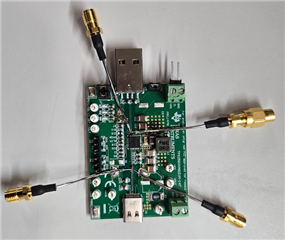
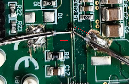
I've tried measuring the S-parameters with the TPS2583XAQ1EVM-147 using a network analyzer recently, but the results were not accurate. I believe it is because of the cables I was using. The conductor side that is soldered on the USB traces are exposed without much of the GND shield (see images below).
I will try again this week by cutting the conductor shorter, but I cannot guarantee that I will be able to deliver what I've committed to. For accurate measurements, we may need to design and build a board with on-board SMA connectors connected to the data pins for this very purpose. I will keep you updated.
After making my modifications, I took a second try at measuring the Sdd21 and generating the simulation file you requested. However, I was unable to improve the accuracy of the measurements today (the results were the same as my previous measurement), so I won't be able to provide the s4p file. My apologies.