This thread has been locked.

If you have a related question, please click the "Ask a related question" button in the top right corner. The newly created question will be automatically linked to this question.

UCD3138A: Unable to read parameters in Fusion Studio GUI

Part Number: UCD3138A

Hello,

I am working on custom 1kW LLC design using UCD3138ACCEVM149 controller card.

But I am facing issues while reading online data from the Fusion Studio GUI when my hardware is powered up and the control card UCD3138ACCEVM149 is placed over it.

The Fusion Studio GUI does not respond at all when the output voltage reaches 8V.

Please suggest any possible means to address the above issue.

Thanks and Regards,

Pratik N

  • Did you use the original firmware? I assume 8V should trigger under voltage protection and output voltage is shut down.

  • Hello Sean,

    Thanks for the reply.

    Let me clarify this. Since working on a custom 1kW LLC board, I have configured the firmware accordingly. So, I am not using the default firmware.

    Also, I am in the process of bringing up the board. So I am gradually increasing the input voltage  from 0 to 380V and the output voltage varies accordingly from 0 to 12V.

    So, I guess it is not the UV protection as the output voltage = 12V is available.

    Is it because of the noise in the feedback current sense signals??

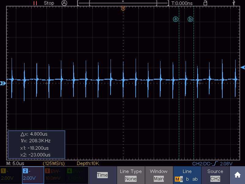
     I_OUT (output current feedback)

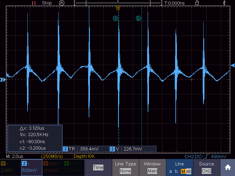
     IPS (resonant current signal)

    Regards,

    Pratik

  • It seems the output still exists, just GUI is not communicating. I think the noise causes the communication failure. You can make the cable farther away from the noise source.

  • Hello Sean,

    I have tried it. But it does not seem to resolve the GUI communication issue.

    Further query, as the above feedback signals captured (I_OUT and IPS) are noisy, does it have something to do with the closed compensation parameters? Because, the output voltage decreases with increase in load.

    I mean to say whether the noise is the primary cause of improper 12V regulation, or it is because of the the improper compensation parameters?

    Thanks,

    Pratik

  • When output voltage drops, does PWM signals are stable? I doubt it hits over power limit.

  • Hello Sean,

    Yes. As the output current increases, the output voltage decreases.

    The converter is designed for 12V, 1kW and I have tried to tune the compensation parameters in firmware.

    Further, as observed, at lower load (say up to 10%), the converter tries to regulate output voltage and the PWM signals show frequency variation to regulate the output.

    But as load increases further, output voltage drops gradually and the PWM signals are fixed at 110kHz, i.e., the set minimum switching frequency.  Gradually as load increases further, the output voltage drops and PWM signals vanish.

    Added to my observation, the output current sensed in the Fusion GUI is higher than actual.

    Regards,

    Pratik

  • Probably the current sensing circuit is wrong, and output higher sensing signal. Please check that.

  • Hello,

    I went on to test the circuit at full load and all the protections disabled in the code. 

    Still the problem persists with the GUI . It does not respond at all.

  • do you mean the firmware/board works fine, just GUI is locked without response?

  • Yes. You got it right.

    The firmware configuration works fine on my custom 1kW hardware board. Only the GUI is locked for some unknown reasons. So, I cannot view the parameters in the GUI while the entire thing is in operation.

  • PMBus cable may be inferenced, sometimes wrap the cable with magnetic core can help. You can try it.

  • I have tried doing that. Unfortunately, it does not help.

  • The noise is coupled to PMBus cable, and it cause communication failure. You can try to improve EMI.