This thread has been locked.

If you have a related question, please click the "Ask a related question" button in the top right corner. The newly created question will be automatically linked to this question.

UCC28950: Primary MOS Failure and Synchronous MOS regulation error

Part Number: UCC28950
Other Parts Discussed in Thread: TINA-TI, PMP8740

Hello,


We are currently testing a PSFB board that is designed based on UCC28950. All the calculations were first verified from the excel tool.

Then the circuit was also simulated and worked properly up to full load of 2.5kW on TINA-TI.


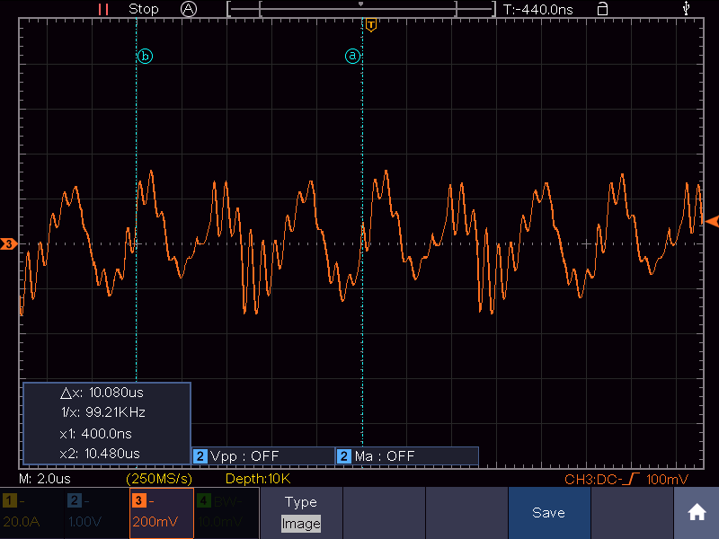
- While testing the board, primary MOS gets blown off shorting the primary side and board does not regulate and produces audible noise.
- Also, when using diodes(IDH20G65C6) instead of MOS on the secondary side. The board properly regulates giving 48Vout up to 17% load(9Amps) before again the primary MOS blows, shorting the primary side.

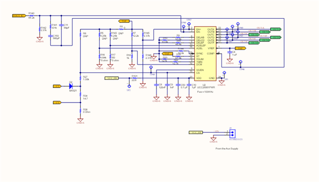
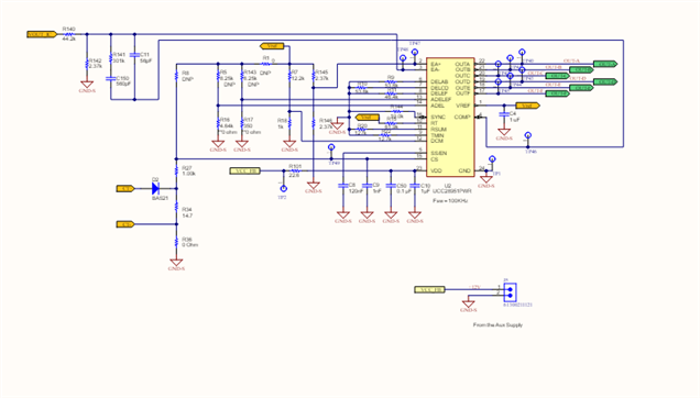
What might be causing this? Can you verify the design once:

PSFB_Sch_Plant.pdfPSFB_Sch_Ctrl.pdf

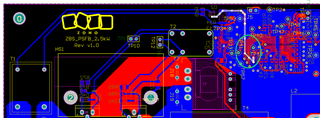
The CS transformer and layout we are using is referenced from PMP8740(with minimal changes)

Regards,

  • Hello,

    Your inquiry is under review and I will get back to you shortly.

    Regards,

  • Hello,

    I reviewed the schematic and everything seems to be functionally correct.

    Fets will get damaged do to any of the following.

    1. Over voltage

    2. Over temperature

    3. Over current

    The following link will bring you to an application note going through the step by step design process of phase shifted full bridge using the UCC28950.  There is a link to and excel design tool in the folder.  You can use these design tools to check your design.

    https://www.ti.com/lit/pdf/slua560

    Regards,

  • Hello,

    I have followed the application note for the schematic I have sent above.

    The current sense signal probed at CS pin of IC through a normal test point pin is more distorted than expected and going below ground.

    Is this happening due to Layout as the current sense circuit is looking good to me?

    (As Highlighted with green circle) I doubt if the CS signal crossing from below the OUT signals is distorting the CS signal?

    Regards,

  • Hello,

    Your inquiry is being reviewed and I will get back to you shortly.

    Regards,

  • Hello,

    The CS signal should never go below ground.  R34 should always be above ground.  Diode D2 prevents current from going in the reverse direction.

    It could be a layout issue.  There may an issue with how R34 is referenced to the secondary ground.  You might want to check your return path to secondary ground.

    If your scope probe is not reference it could distort the signal.  I just want to double check that your scope probe is reference to the secondary ground.  You should be able to connect it to TP1.

    Regards,

  • I doubt if this is a problem caused due to probing. 

    As you mentioned this might be due to layout issue, in this layout what changes about the CS signal do you suggest to eliminate the issue.  

    Regards,

  • Hello,

    Your inquiry is under review and I will get back to you shortly.

    Regards,

  • Hello,

    Your current sense signal should not go below ground.  I have put your schematic and could you show me how there is a negative current that goes through R34 to developed to develop the negative current sense signal.  This is why I thought you had a probing issue. 

    You should double check your probe ground.  If it is not that then there is most likely something wrong with your layout, schematic and/or build. 

    The CS signal should not go below ground.

    The UCC28950 data sheet does give recommendations on layout that you may find helpful as well.  Please note that there is a 600 W reference design that uses the UCC28950 that has a proven layout.  You can find it at the following link.  You can use it to compare it to your layout. 

    https://www.ti.com/lit/pdf/sluu421

    In regards to your current sense transformer.  You should also check the current through the primary and secondary to make sure it is working correctly.  You will need to current probes to do this.

    Regards,