This thread has been locked.

If you have a related question, please click the "Ask a related question" button in the top right corner. The newly created question will be automatically linked to this question.

TPS25762-Q1: Troubleshooting tips?

Part Number: TPS25762-Q1

I've assembled a basic design, based on figure 10-3 of the datasheet. The only significant difference is I don't have anything connected to the NTC pin, but I have disabled thermal foldback in the GUI.

Firmware was loaded into the device with an EEPROM programmer and I can successfully update it via the USB endpoint when I power it up in update mode.

From a cold start, the device appears to power up and draws around 7mA. I can see a 400kHz signal on the SYNC pin, the LDO's all seem to output the right voltage.

However, there is no sign of any activity output on the USB port.

Are there some recommended troubleshooting steps?

  • Hello Phillip,

    1. What is VIN?
    2. What is the TVSP setting when testing the USB port's output? Are you powering the board up in EEPROM mode?
    3. What exactly are you connecting to the USB port? 
    4. When you say there's no signs of activity, are you referring to the voltage and current? So 0V and 0A?
    5. Which base FW version are you using to generate the binaries you are programming the EEPROM with? And which GUI version are you using? Are you using the latest?
    6. Do you have a TPS25762-Q1 EVM? If you do, are you observing the same behavior when you program the EVM with the same binary?
    7. Can you save the GUI configuration and share the JSON file along with the binaries you are programming your board with?

    BR,

    Seong

  • 1. VIN is 12V

    2. When testing, TVSP is essentially open, Rdamp is 10ohm into a 0.47uF cap and Cdamp is 100nF

    3. I've tried a USB port monitor as well as some simple devices like headphones

    4. Yes, no voltage is present at Vout

    5. Firmware is F311.03.10.0003 and GUI is 1.4.0

    6. No, I don't have the evaluation module

    7. Not sure how to attach the files here :-(

  • Hi Phillip,

    1. Which USB port monitor device are you using? 
    2. Type-C Headphones will not work with the TPS25772 as the device does not support data role swap. Have you tried connecting a device such as a phone? Do you have the part number of the USB cable you are using?
    3. Are the I2C signals broken out to header pins so you can read and write via the I2C bus?
    4. You can attach files by clicking Insert -> Image/video/file.

    BR,

    Seong

  • Well, good news! I connected up an iPhone and it springs to life. Takes a few seconds to activate and works its way up to about 5W, but that could be capped because the iPhone already had a fairly full battery.

    I had expected voltage to be present at idle, but obviously not with this configuration.

    Is this possible? To have it default to 5V for dumber USB devices?

    Are there recommended test devices to validate other PD profiles?

  • Hello Phillip,

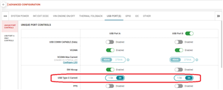
    VBUS will always default to 5V for non-PD Type-C devices. The non-PD Type-C current can either be configured to 1.5A or 3A via the GUI's "USB PORT(S)" tab (see image below).

    I personally use the Power-Z KT002 or KM003C. The PassMark PM125 is another reliable PD tester that can also be used as a load.

    BR,

    Seong