This thread has been locked.

If you have a related question, please click the "Ask a related question" button in the top right corner. The newly created question will be automatically linked to this question.

LM25184: Eval Board LM25184EVM Input Current Very High at Startup

Part Number: LM25184
Other Parts Discussed in Thread: LM5185, LMQ66420, LMQ66430, LMR36520

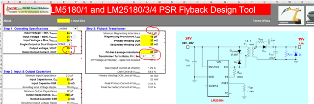
This post is related to an earlier post “LM25184: Flyback eval board output loses regulation”. I am using eval board LM25184EVM-S12.  My goal is VDC-in = 24V, VDC-out = 24, IDC-out = 1 A.  I made the modifications required from the related post but was losing output regulation during low power heat runs.  It was then recommended that I increase the inductance of the transformer from 7.5 uh up to greater than 13uh.  The one I wound measures 14.5 uh and .31 uh leakage. 

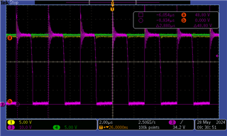
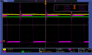
I am able to get to 24V-out and have successfully increased the output current in steps up to .642 A so far.  The problem I am having is this.  At these higher output current levels, when I turn on the DC supply (BK #1610), the DC supply goes into output current limit and clamps the supply voltage, so the eval board cannot start.  Why is the input current draw so high (over an amp)?  Is that normal?  Here is my last data.  For me to be able to run at this level I had to bring in a partial load so that it started and then parallel the load resistance with enough resistance (while running) to get to the current level I was testing for. 

Vout = 24 V

RL = 37.4 ohm

Iout = .642 A

F = 223.21 kHz, Duty Cycle .504

Idc-in = .808

Pdc-in = 19.4 W

Eff = .794

What level of input current from the 24VDC supply can I expect to see while starting into a 1 A output load?  Also, the surface temperatures during the heat run (1 hour) were as follows.  Are these expected to be this high?  Is there something I can do to or change to reduce this?

LM25184 = 117 F,

D2 (3SMAJ5938B) = 149 F,

D1 (SS30100HE_R1_00001) = 114 F

Thank you - John

  • Hi John,

    Thank you for using the LM25184.  What is your ambient temperature during your 1 hour heat run?  

    Regarding the inrush current, what is your power source current limit level?  Anyway, you may consider to increase the Soft-Start capacitor (C12 on the EVM) to reduce the inrush current.  Try 100nF up to 470nF and see if you can prevent tripping your source's current limit.

    Thanks,

    Youhao

  • Hi Youhao,


    The ambient temp was 74 F.  The current limit of the source supply is 1 A.

    (edit):  I am removing the post regarding the failure.  That was my mistake - incorrect ground placement.  I will continue with my heat run currently at 24Vout and .71 A output.

    John

  • Hi John,

    Thank you for the updates.  I don't see anything very wrong with your temperature reading.  You may consider to improve the heat dissipation for D2, maybe use a larger sized diode, or increase the PCB thermal pad?  Anyway, what is D2 for?  The output rectifier diode? 

    Thanks,

    Youhao 

  • SUSALB-KM-C24052312060.pdf

    D2 is the Zener to control spikes on the primary side of the transformer - I think to protect the internal switching mosfet.  You had me change it from 20 V to 36 V when we went from 12 V out to 24 V out.  Here is the modified schematic with your recommendations.

  • Hi John,

    Thanks for reminding me.  If 149C on D2 is really a concern for you, you may consider to increase the PCB thermal pad of D2 to get better heat dissipation through PCB. Increase either the width of trace to the pads or the pads themselve will increase the copper area and help thermal dissipation.

    Best Regards,

    Youhao

  • Youhau,

    The past 2 times I have reduced the load resistance (to achieve higher output current) the output voltage has been getting lower.  The load resistance is now 25.7 ohms and the output voltage is 21.87 V.  that is 0.85 A.  The input voltage is 24.04V and the supply limit from the supply is 10 A so I know I am not limited on the input. The run before this was 28.2 ohms and the output voltage was 23.48 V.  All runs at lower resistances gave 24 V out.  Is there a reason why I can't get to 1.25 A (data sheet rating)?

    I tried increasing the voltage feedback resistor from 238 k to 243 k and it made no difference.

    In the images above: grn  = Vout and mag = Vsw, Yel = Vdc at top of transformer.  The left image is at 56 ohm (light) load and the right is at 25.7 ohms (heavy).  It can be seen that at light loads Vout is 24 V and Vsw = 48.8 V.  At 25.7 ohms Vout falls to 21.8 V and Vsw falls to 46.2 V.  VDC voltage (from ground to the top of the transformer) stays at 24 V in both cases.

    What would be causing the voltage at the sw node to drop.  I measured the pk-pk voltage on the primary and secondary of the transformer.  At light load the voltage is 48.2 Vpk-pk but at heavy load the voltage is 45.2 Vpk-pk

    Added 5/29/24

    I reduced the output voltage to 19V and then tried different values of load resistance to see if I could get above .85A out.  The highest I could get was .931 A and then the output voltage began to drop.  Here is that data.

    Rload              Vout (V)          Iout (A)           Pout (W)          Fsw (kHz)       DutyC             Vspike

    56.7                 18.92               .334                 6.32                 340.1               .387                 66.8

    25.7                 18.92               .736                 13.92               193.05             .444                 65.6

    24.3                 18.92               .779                 14.73               181.16             .442                 69

    22.3                 18.92               .848                 16                    167.79             .443                 68.6

    21.3                 18.93               .889                 16.8                 156.74             .445                 68.6

    19.6                 18.25               .931                 16.99               105.11             .304                 68.6

    John

  • The responsible engineer is out of office now and TI responses may be delayed. Thank you for your patience.
    -EL

  • Hi John,

    Can you share your transformer datasheet, including primary inductance, turns ratio, and Isat?  if you also know the Rdc of the windings, let me know those, too.  By the way, I am on a biz trip, so please pardon me if my reply delays.

    Thanks,

    Youhao

  • Youhau,

    I don't have a data sheet.  I made the transformer myself.  The details are as follows. 

    The core is a P30/19 (TDK# B65701W0000R087)

    Coil Former is TDK #B65702B000T001

    Core Clamp is TDK #B65705B003X000

    The primary is 2 turns of #22 magnet wire but is actually 2 wires in parallel.  The secondary is also 2 turns of 2 parallel #22 wires.

    I had to put a .0005" plastic shim between the 2 core halves to get the inductance I needed.  Before the gap it measured the primary measured 20.9 uh.  After the gap the measurements were:

    RatioP-S = 2:2

    Lpri = 14.52 uh

    Lsec = 14.45 uh

    Lleakage = 0.31 uh (measured on primary with secondary shorted)

    C pri-sec = 2.6 pf

    I calculate the total primary wire resistance to be about .00618 ohms (same for the secondary).

    John

  • Hi John,

    The engineer in charge of this is currently OOO and will be back next week. Appreciate your patience,

    Thanks,

    Richard

  • Youhau, I made me a new transformer instead of 2:2, I went to 3:3 keeping the primary inductance at 13.47 uh.  I was able to get up to 1.02 A before the voltage started to fall below the desired setting (19V).  Thinking I was making progress, I made a 4:4 ratio transformer.  This time the voltage was very unstable and eventually blew something on the eval board.  I have ordered another board.  I need to get some input and guidance.  To restate, I need to get to 24Vout and another design at 19 V out with 24 V in and up to 1.1 A out.  It looks like I am just squeaking by here.  Would a different chip or eval board be better suited for me.  I am spending a lot of time on this.

    John

  • Hi John,

    Did you ever used our design calculator to help you design, which can be downloaded at the following link?

    https://www.ti.com/tool/LM25183-LM25184DESIGN-CALC

    I just ran your numbers in, and the calculator showed it would not deliver 24Vout @1.1A, and it seems hitting the IC's maximum power capability.

    For your 19Vout design, if you also want to get 1.1A, you may consider to use a 3:2 or 6:4 transformer, with Lmag >15uH, and you should be able to deliver at least 1.2A load under 24Vin.

    For your 24Vout  1.1A design, you may choose our LM5185 converter, for which the external MOSFET is used you can scale the power up.

    Best Regards,

    Youhao

  • Youhao,

    I have been following your suggestion using the LM5185.  I was inputting the values that are already on the 5185 Eval board.  It looks like I should be able to get over 1A at 19V out and 24 Vout with an input of 24V.  However, it looks like I might be too close to a current limit on the Rcs resistor at the source of the Mosfet.  The transformer data sheet says 5.5A Isat.  If I change Rcs to 18.5mohm that should let me run 1.125A out. 

    Can you look the eval board over and tell me what other components I need to change in order to get to 24V out at 1.125A?  Also, I don't understand Step 8 in the excel tool - Compensation Design.  I see the recommended values for Rcomp, Ccomp, and Chf but I don't know what this is doing or what may go wrong if the values are not correct.  There is a pull-down menu to select the desired crossover freq and that makes the components change due to the frequency that is selected, but there is no guidance on how to select the frequency or why.  Can you help me understand that?

    Regards - John

  • Hi John,

    Yes you can reduce Rcs=18 to 19mOhm and the circuit should produce 24V for 1.125A:  note that there is 10% margin included in the calculator.

    Remember to change the output Zener from 18V rated to ~26V rated if you want to have 24V out.

    Step 8 is for the feedback stability.  You may not need to touch those if the dynamic response is good enough for your application.  If you wish, you may increase R17 to 24.9k for faster response.  You may refer to a Power Electronics text book for feedback loop stability discussions.  Basically the Body Plots should have adequate Gain and Phase Margins. 

    Thanks,

    Youhao

  • Hi Youhao,

    I have change all the components as described above.  Now I am waiting on the resistor to adjust the feedback to 19V out.  I have a related question.  I started with the flyback because I have a 24V source and need 19V out.  Could this be tackled as well and maybe easier if I used a Buck converter.  Does TI have an evaluation board and a calculation tool to help me test a 24Vin and 19V out at at least 1.25 A out? I saw many controller types but could you point me to one that could simple to modify and also has a calculation tool?

    Regards - John

  • Hi John,

    I thought you need isolated output. If it is not a case, sure that you can use a buck. There are many options,  but I think you can take a look of LMQ66420/30 for fewer external components. 

    Thanks,

    Youhao

  • Yes Youhao, I do need isolation but currently I am using medical grade 24:24V converters.  I was going to replace them with isolated 24V:19V flyback.  Now I am wondering if it would be easier to just put a buck regulator on the output of the 24:24V converter to get me down to 19V and the isolation will still be with the original converter.  I looked at the LMQ66430 and the tool said the output will be only up to 18V.  Maybe there is a minimum voltage differential from input to output and I'm not meeting it with the 24V input.  Do you have another one I can look at?

    John

  • Hi John,

    My bad,  I forgot the voltage rating. It is because the OUT and FB share the same pin and the control circuitry has a max voltage limit.  

    If you want 19V in your isolated output rail, you do not have to use the buck though. The flyback should produce well regulated 19V once you get the setting correctly.  In a fast path if you still want to consider the use of a buck, please take a look at LMR36520.

    Best Regards,

    Youhao