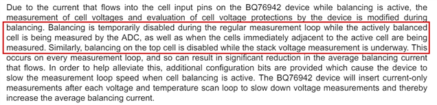
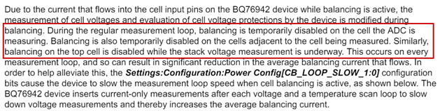
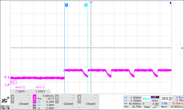
This thread has been locked.

If you have a related question, please click the "Ask a related question" button in the top right corner. The newly created question will be automatically linked to this question.

BQ76942: the cell balance of AFE-BQ76942

Part Number: BQ76942

Dear TI experts,

      We have used your company's BQ76942 chip, but encountered an issue. During the battery charging process, we found a symmetrical voltage jump between CELL1 and CELL2 displayed on the computer(Figure 1). Subsequently, we captured the voltage of the battery cell using an oscilloscope and found that the period of voltage jump of the battery cell was consistent with that when the battery was balanced(Figure 2-4)    .
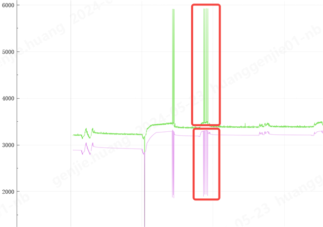
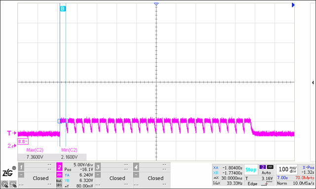
As far as I know, corresponding cell sampling should not be performed during battery balancing. We want to know the reason for this situation? How to solve it?Looking forward to your reply!

  • Hello GJ,

    For this device cell sampling is also performed during cell balancing, during the measurement cell balancing stops so that the measurement reported by the BQ76942 is not affected by the cell balancing.

    This is described in Section 15.1 Cell Balancing Overview of the datasheet, see datasheet excerpt below:

    It is also described in Section 10.2 Cell Balancing Timing of the Technical Reference Manual, see excerpt below:

    So cell this will cause balancing to stop momentarily when the cells are being measured. As described in this same section, it is also possible to change how frequently the voltage of the cells are being sampled when they are being balanced, so that more balancing time is achieved, this is done by changing the Settings:Configuration:Power Config[CB_LOOP_SLOW_1:0] setting.

    Section 5 Timing Information of the Cell Balancing With BQ769x2 Battery Monitors application note also explains this and shows examples of how the cell balancing looks at different CB_LOOP_SLOW settings.

    I hope that answered all your questions on it! Slight smile. But if you have any more questions, please reach out!

    Best Regards,

    Luis Hernandez Salomon

  • Hello GJ,

    Looking back at this, I think I misunderstood your question at first!

    Is it possible to check the connection to CELL1? If there is not a good connection between the cell and the BMS board then this could increase the resistance in the cell path, which could potentially cause what is shown in the first image you showed. This image looks very similar to what an Open-Wire condition would look like, which could happen with high input resistances due to loose connections.

    Best Regards,

    Luis Hernandez Salomon