This thread has been locked.

If you have a related question, please click the "Ask a related question" button in the top right corner. The newly created question will be automatically linked to this question.

TPS62933: TPS62933FDRLR not able to convert 28V to 1.2V and 3A output

Part Number: TPS62933

Hi Team,

We are working power circuit of below requirements

Vin =28V

Iout=3A

Vout=1.2V

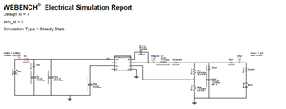
We have simulated as shown below.

------------------------------------------------------------------------------------------------------

Electric BOM as given below

Name Manufacturer Part Number Properties Qty Price Footprint
Cboot MuRata GRM155R71A104KA01D
Series= X7R
Cap= 100.0 nF
ESR= 1.0 mOhm
VDC= 10.0 V
IRMS= 0.0 A
1 $0.01
0402 3 mm2


Cin TDK C3216X5R1H106K160AB
Series= X5R
Cap= 10.0 uF
ESR= 1.0 mOhm
VDC= 50.0 V
IRMS= 4.9 A
1 $0.24
1206_180 11 mm2


Cinx TDK CGA3E2X7R1H104K080AA
Series= X7R
Cap= 100.0 nF
ESR= 29.6 mOhm
VDC= 50.0 V
IRMS= 971.99 mA
1 $0.01
0603 5 mm2


Cout MuRata GRM32EC80J107ME20L
Series= X6S
Cap= 100.0 uF
ESR= 1.0 mOhm
VDC= 6.3 V
IRMS= 6.0 A
2 $0.17
1210_270 15 mm2


Css MuRata GRM155R71A333KA01D
Series= X7R
Cap= 33.0 nF
ESR= 1.0 mOhm
VDC= 10.0 V
IRMS= 0.0 A
1 $0.01
0402 3 mm2


L1 Bourns SRU1038-2R2Y L= 2.2 μH
7.7 mOhm
1 $0.43
SRU1038 144 mm2
Rfbb Vishay-Dale CRCW040210K0FKED
Series= CRCW..e3
Res= 10.0 kOhm
Power= 63.0 mW
Tolerance= 1.0%
1 $0.01
0402 3 mm2


Rfbt Yageo RC0603FR-074K99L
Series= ?
Res= 4.99 kOhm
Power= 100.0 mW
Tolerance= 1.0%
1 $0.01
0603 5 mm2


U1 Texas Instruments TPS62933FDRLR Switcher 1 $0.30
DRL0008A-MFG 9 mm2

---------------------------------------------------------------------------------------

We are not able to get 1.2V output. TPS62933FDRLR IC is getting burnt.

Please let me know input current rating and if any issues with above circuit. 

  • Hi Ajit

    Did you tested the TPS62933 and got the issue? Can you please share the schematic and the test condition that it get burnt?

    Thanks and best regards.

  • Hi Gui,

    Yes, we tested it and got the issue.

    Steps:

    • Provided input voltage 8.0V and input supply current at 0 amp.

                          Observed Output: 0.0 V across Cout

    • Increased input current by 0.01A

                          Observed Output: 0.0 V

    • Increased input current to 1A.

                          Observed Output: 0.0 

    • Provided input voltage 10V, with supply current 2A. Observed Output: 0.0 V

    • We have also tested with 28V input then IC got burnt.

    Please let us know if any issue with schematic or test process.

    Appreciate your support on this!

  • Hi Ajit

    This is the webench simulation circuit, can you please share the schematic of your test circuit? 

    ------------------------------------------------------------------------------------------------------

    • Provided input voltage 8.0V and input supply current at 0 amp.

                          Observed Output: 0.0 V across Cout

    • Increased input current by 0.01A

                          Observed Output: 0.0 V

    • Increased input current to 1A.

                          Observed Output: 0.0 

    • Provided input voltage 10V, with supply current 2A. Observed Output: 0.0 V

    -------------------------------------------------------------------------------------------------

    Do you mean the circuit cannot operate when Vin is 8/10V? Is the EN shutdown?

    • We have also tested with 28V input then IC got burnt.

    Did you use a DC source to do the test? There can be an overshoot if the input cable is long and without a ceramic input capacitor.

    Thanks and best regards.

  • Hi Gui,

    We have soldered all components mentioned in above BOM and simulation circuit on a breadboard and tested it. So, circuit diagram is same as simulation.

    Q: Do you mean the circuit cannot operate when Vin is 8/10V? Is the EN shutdown?

    A: We have increased Vin from 8V to 28V in 2V steps. But we got 0V at output.

    Q: Did you use a DC source to do the test? There can be an overshoot if the input cable is long and without a ceramic input capacitor.

    A: Yes we have used DC source to test. Input cable length is 1/2 feet.

  • Hi

    Please let me check and get back later,thanks.

  • Sure, please let me know.

    Thanks!

  • Hi Ajit

    The schematic and the BOM looks good to me. The EN /RT floating should also be fine. The circuit should be able to output the target Vout. Is there any possibility there can be any wrong wire connection? 

    You can also do some test and record the waveform: 

    Measure the EN, SS waveform when start up  (when Vin is powered on);

    Measure the Vin, SW, iL when start up / steady state. 

    That may help us identify what goes wrong. And can you please replace with a new device and do the test?  Thanks and best regards.

  • Thanks Gui, its working now

  • Thank you for noting, I will close this thread now. Please let us know if there are other questions.