This thread has been locked.

If you have a related question, please click the "Ask a related question" button in the top right corner. The newly created question will be automatically linked to this question.

TPS92201A: PWM Dimming Problem

Part Number: TPS92201A

Tool/software:

Hello,

I recently completed assembly of a design using TPS92201ADRVR. While my LEDs light up just fine, they seem to be at 100% brightness all the time and PWM dimming does not work. I'm unsure of what could cause this, but if someone could provide some input on what I'm doing wrong it would be very helpful.

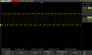
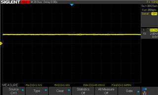
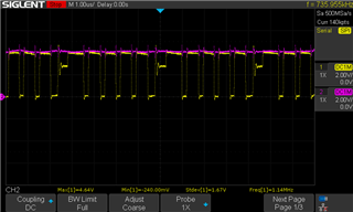
There are two images from my oscilloscope attached. One is the PWM signal from an ESP32, running at 20% duty cycle and 25kHz frequency. The peak voltage is 3.5V, so it meets the high-level voltage threshold for TPS92201ADRVR, and I already checked that the signal meets the minimum PWM on time requirement specified by the datasheet. The second is Vfb, it has a minimum of 80mV, mean of 233mV, and maximum of 640mV.

Additionally, varying the duty cycle of the PWM signal has no affect on the amount of current the device draws. My schematic is attached. I am using Rsense=125mOhms based on needing 800mA current at Vfb=100mV.

Thanks and I appreciate any insight you might be able to offer.

  • Hi Max,

    Our expert will give you reply later.

  • Hi Max,

    Please be noticed that TPS92201A only supports analog dimming, but not PWM dimming.

    May I understand what is your input voltage and LED forward voltage? It would be better if you could provide the I-V curves of the LEDs.

    Best Regards,

    Steven

  • I see in the datasheet "Analog dimming is achieved by adjusting the duty cycle of the PWM input with 1% to 100% range" -- so if not via the PWM pin and adjusting duty cycle like I am now, how else would I achieve dimming?

    Here's the I-V curves:

  • Hi Max,

    Please be noticed that TPS92201A only supports analog dimming, but not PWM dimming.
    "Analog dimming is achieved by adjusting the duty cycle of the PWM input with 1% to 100% range"

    It is just a kind reminder that you are using analog dimming, but not PWM dimming :)

    May I understand what is your input voltage? 

    Best Regards,

    Steven

  • No problem I was just thinking maybe I missed something in the datasheet about analog dimming.

    Input voltage is 3.3V

  • Just for clarification, each channel R/G/B/W has its own TPS92201A. R_sense values are 125m, 125m, 140m, 140m respectively based on the specified current requirements from the LED's datasheet. There are four RGBW LEDs total, and their color channels are in parallel.

  • Hi Max,

    Please provide the LED forward voltage at the output current you set and please make sure your input voltage is higher than this forward voltage.

    Please measure the SW waveform and the inductor current, and then show me the oscilloscope capture and your test condition. Thanks.

    Best Regards,

    Steven

  • Hi Steven, thanks for all your input so far. For these measurements (as well as the previous waveforms) I am using the red channel. Attached is the SW waveform. The current through the inductor is 0.59A. In subsequent tests with duty cycles from 10-100% the current remained the same. I used 4V as the voltage input here. PWM duty cycle was set to 30%. Also, if this is relevant, I am using the standard 10uF capacitor/2.2uH inductor (part number SDER041H-2R2MS) as suggested by the datasheet.

  • Hi Max,

    The SW waveform looks unstable. Could you measure the VIN node and show me the oscilloscope capture (together with the SW waveform)?

    Best Regards,

    Steven

  • Hi Steven, attached are two images, one of just Vin and one of Vin with the SW waveform (I had to cut some traces to measure inductor current, so this is on the green channel if that matters at all). In the photo with two channels, purple is Vin and yellow is SW.

    I could definitely see how this could be problematic. I am using a cheap benchtop power supply to test these -- maybe the next step is finding a better quality power source?

  • Hi Max,

    I could definitely see how this could be problematic.

    The input power rail does not look good based on the above picture. Please add more input capacitors or use a power source with better quality and have a try.

    Best Regards,
    Steven