This thread has been locked.

If you have a related question, please click the "Ask a related question" button in the top right corner. The newly created question will be automatically linked to this question.

TPS6594-Q1: Not powering up, DRA829 configuration

Part Number: TPS6594-Q1
Other Parts Discussed in Thread: DRA829,

Tool/software:

Hello TI guys, 

My team and I have implemented the  PMICs on Two different boards to power the DRA829.

PMICs being used: TPS65941213-Q1 and TPS65941111-Q1

Neither do power up...

(Each board have it's own problems but I've manage to get one close to functionnate.. I think?)

We've corrected lots of problems but the PMICs remains OFF and i don't have any more clues.

remaining schematic differences:

signal PROC112A41 Our Borad Symptom
SEL_SDIO_3V3_1V8_n to SoC WKUP_GPIO_9 (G26) To SoC UART1_RXD (AA4)  read as "0" in GPIO register, should be 1
H_DDR_RET_1V1 pull up to 1v1 Actually the pull up is broken, will fix it on monday  ?

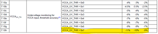
remaining registers difference (PMIC B):

PMIC  register name
what it says interpretation
PMIC B 3F GPIO_IN_1
relates to the SEL_SDIO_3V3_1V8n signal is that a problem ?
PMIC B 5A INT_TOP
FMS + MODERATE + MISC + LDO
Why "LDO_VMON_INT" ? LDO registers are ok
PMIC B 5F INT_LDO_VMON
VCCA_INT
PMIC B 62 INT_VMON
VCCA_UV_INT
how is it possible if PMIC A is ok ?
PMIC B 67 INT_MODERATE_ERR
BIST_FAIL
PMIC B 69 INT_FSM_ERR
MCU_PWR_ERR + ORD_SHUTDOWN
Can't find the source of that


Could you please look into the attached documents and tel me what seems wrong ?

Register Comparison_forTI_01.xls

Used documents:

- slvuc99a.pdf
- TPS6594-q1.pdf (slvea7b)
- proc112a1(001)_SCH.pdf
and others

(and thanks to those guys the excel files are really helpfull https://e2e.ti.com/support/power-management-group/power-management/f/power-management-forum/1351129/pmics-not-powering-up-tps65941213-q1-and-tps65941111-q1-dra829/5171816?tisearch=e2e-quicksearch&keymatch=DRA829#5171816)

  • Hello Marine,

    Based on your register dump, the VCCA is hitting the UV threshold on PMIC-B. The UV threshold is -10% nominal from 3.3V, but from the data sheet there is some acceptable variance.

    The VCCA UV threshold is not the same as the UVLO threshold. UVLO will cause an immediate shutdown and clear the interrupt registers as well. UV will cause an orderly shutdown and then a recovery attempt. 

    VCCA is considered an MCU rail and is reason for the MCU_PWR_ERR. 

    Please measure the VCCA voltage. It would be best to do this with an O-scope while triggering on nINT pin.

  • Hi Michael, 

    Thanks for your reply, just after my question I had time to try and measure many things, you were right something was wrong around the main  supply.


    We made a hundred test and I wouldn't bother you if we had still path to explore.

    After all those tests and soldering we found that it was a LDO that was over loaded it draw to much current on the main supply,  it disturbed it and triggered the FB_3 threshold...

    Anyway its now powering up.

    Thanks for your time.

    Marine.