This thread has been locked.

If you have a related question, please click the "Ask a related question" button in the top right corner. The newly created question will be automatically linked to this question.

TPS546D24A: Bringup Troubleshooting for 2-phase configuration

Part Number: TPS546D24A

Tool/software:

Hi,

I've designed a 2-phase D24A based buck converter to get 1V2 60A output out of 12V input. I've used TPS546D24AEVM-2PH schematic. Changed the coils to 2 x 1uH, and a VSET resistor to ground to move from 0V8 to 1V2. Rest ir pretty much the same. Board is 4 layer as that should basically be more than enough to the project.

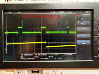
Supplied 12V. What is happening after powering up is that the bucks are buzzing. The output signal is a kind of a sawtooth going form 0,3V up to about 1,4V. I observed that when output voltage crosses 1V2 it pulls the PG on the SLAVE high. On the master the PG signal remains always 0.

There is shourly some communication on BCX lines as well as on SYNC line.

I checked every bit of the design and compared against the reference design. Did not find anything critical that might seem to couse that kind of strange behaviour.

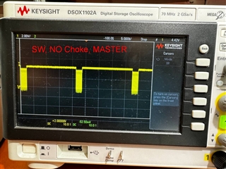
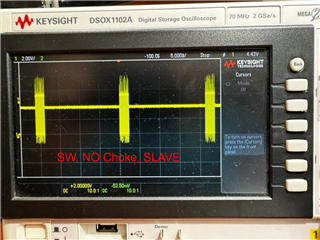
Just out of curiosity I desoldered both chokes to measure SW signal on both devices. Suprisingly they are somehow different.

On Master the SW signal oscillates around 4V and going from aprox -1V to +8V. While for the slave device it would also go with 4V line with the osccilations but ranging only form -1V to +3,8V. I have no idea why is there any difference - FYI as an observation.

Suspected bad soledering altgough just for the sake of testing that I swapped the IC however the result was the same. That's not the case than. Had build second sample of the board - Same result also though.

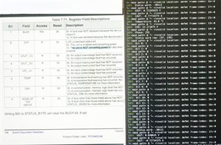
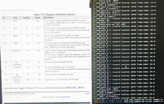
I did not connected it via PM-BUS yet so cannot read error flags at the moment - Waiting for my colegue to code that for me.
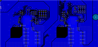
Schematic:

0247.SCH.pdf

Oscilloscope measures:
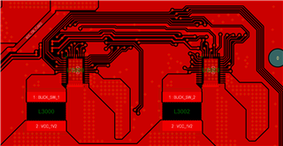
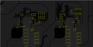
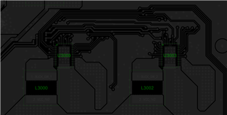
Layout:

  •  

    The 2-phase EVM uses a 150nH inductors with 4x 470μF + 24 47μF capacitors

    Your design is using 1.0μH inductors 10x 100μF capacitors.

    Those changes in the power stage are likely to require significant changes to the compensation loop.

    You increased the inductance by 6x, then decreased the current loop gain from 4x to 3x.  That combination reduces the current loop bandwidth by a factor of 8.9 (About 89%)

    You then decreased the capacitance from 3,000uF to 470uF with the same voltage loop gain, which increases the voltage loop bandwidth a factor of 6.4

    The combination is simply not stable, leading to the issues you are seeing.

    Unfortunately, I don't think there will be a compensation combination through pin-programming that will stabilize 1.0uH inductors driving 10x 47uF capacitors in a 2-phase configuration. 

    Why are you using such large inductors?  12V to 1.2V @ 550kHz, a 1μH inductor has less than 2A of peak to peak ripple.  We generally recommend selecting inductors for 20-40% full load current ripple.  For 30A/phase, we would recommend selecting 150nH - 330nH for the inductor, not 1.0μH.

    For L = 150nH, you can stay with the 4x ILOOP gain options used in the EVM.  If you select a larger inductor value, increase ILOOP proportionally, upto 7.

    10x 470uF is not a lot of capacitance for a 60A load, but if you stabilize the current loop with a properly sized inductor, the VLOOP gain of 0.5 will reduce the voltage loop gain enough to work with the 10x 470uF output capacitance, but the transient response wont be great.  If you need better transient response, you will need to add more output capacitance.

    Do you have a dynamic load current and allowable drop or rise of VOUT during a load change?

  • Thanks for the response!

    To be honest I am not sure why did I go with such high inductance values as 1uH. Also I don't have anything lower on hand so need to wait with a package to come. That may take a few days.

    Separatelly we ware able to read from the device and the result is as follows reporting bits 0, 5, 6, 9, 11 and 15 as "1" in (79h) STATUS_WORD Register.

  • Did some extra testing.

    I’ve changed inductors from 1uH to 150nH that I borrowed from TPS546D24AEVM-2PH. Added 2x1000uF bulk capacitors on 1V2 output as well as 2x1000uF on the 12V input rail. The result is exactly the same. The converter ramps up the voltage, crosses the 1V2, pulls the PG high. Despite that it continues to go up with output voltage till about 1.45V. And than restarts the cycle. It restarts every ~9ms which is about 115Hz. And all that even without any load on the output.

    Added 1.5R resistor to the output to see what happens as any load given. It stops buzzing but gets stuck around 350mV…

    Just out of curiosity I’ve soldered the 1uH inductors to the EVM-2PH evalboard and yet it still works fine. Therefore definitely seems like not the problem with inductor or capacitance values (at least for light load).

  • Got that figured out ultimately. I believe the picture will speak for itself:

    Test conditions: 150nH inductors, added 2x1000uF electrolytic capacitors on the 1V2 output as well as 2x1000uF on the input 12V rail. Freq 550Hz. Checked with oscilloscope that the bucks are working interleaved. I see some voltage ripple on the output (when loading with ~45A load as this is target load anticipated). Also it work only for a minute and than overheats. What should I dial to make it better?

  •  

    The image you added did not come through.  While the Web Interface will allow you to paste images, and will display them, you need to use the "Insert"  "Image/Video/File" tool from the bottom menu to upload the image, otherwise it wont display.

    The status bits you are seeing are all indicating an output over-voltage (VOUT_OVF) which is likely a result of the problems with compensation compatibility with the inductors and output capacitors.

    Do you happen to have the ESR value for the 1000μF capacitors you are using on the output voltage?

    Are all of the input and output bypass capacitors on the opposite side of the board from the TPS546D24A converters?

    As a first step, I would recommend using our design tool available on the product folder

    https://www.ti.com/product/TPS546D24A 

    https://www.ti.com/product/TPS546D24A#design-tools-simulation 

    https://www.ti.com/tool/download/SLURB01