This thread has been locked.

If you have a related question, please click the "Ask a related question" button in the top right corner. The newly created question will be automatically linked to this question.

TL494: Fixed duty cycle value and dead time

Part Number: TL494

Tool/software:

Hello,

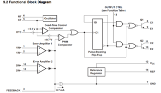
I am trying to design a Full-Bridge DC/DC converter. Planning to use TL494 IC. I have some questions about IC's pins as well as duty cycle and dead-time value.

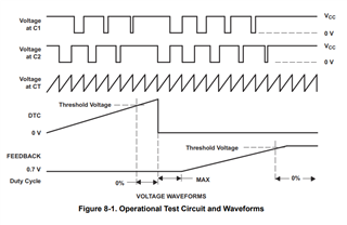
  1. I want fixed %35 duty cycle value. How can I adjust this?
  2. Dead-time value can be minimum in  the begining but later I may change it. So what kind of configuration (maybe using 0 ohm resistor) I should do?
  3. I don't know what I am going to do with pins 1, 2, 16, 15 and 3. Should I tie them like page 8 in datasheet? If it is so, what about pin 3?

Thank you so much for your time and considerations

Regards

Nafi Can

  • Hi,

    You can look at section 9.1 block diagram to find how to do.

    1. pin 1 and 16 grounded, pin 2 and 15 to REF, and then adjust pin 3 to get 35% duty cycle

    2. since you set up 35% duty cycle so any time between the duty cycle is off time or dead time so you cannot make dead time smaller that.

    3. see #1 above

  • Hi Hong,

    Thank you for your response,

    So, I am going to tie pin 2 (1IN-) and pin 15 (2IN-) to pin 14 (REF) via 50k resistor, pin 1 (1IN+) and 16 (2IN+) to ground.

    When it comes to pin 3 (FB), I may tie it to ground by using a resistor and then find the value of it to adjust 35% duty cycle. OR I can use a potentiometer from REF to GND adn connect the wiper to the FB pin, then I will adjust the 35% duty cycle.

    Can you please confirm my connections?

    Thanks in advance

    Nafi Can

  • Hi,

    Yes, you can do these. Also DTC needs a connection - you can tie it to GND or follow the datasheet.