


Tool/software:
Hi team,
my customer has done some test as below.
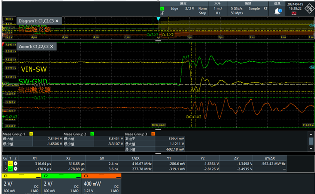
1. when output short to gnd, the VIN-SW voltage will be -1.6V@5ns;and the SW-GND voltage will be -3V@2.8ns.Dose this have some risks for our device? pls see the attached for details.
Tool/software:
Hi team,
my customer has done some test as below.
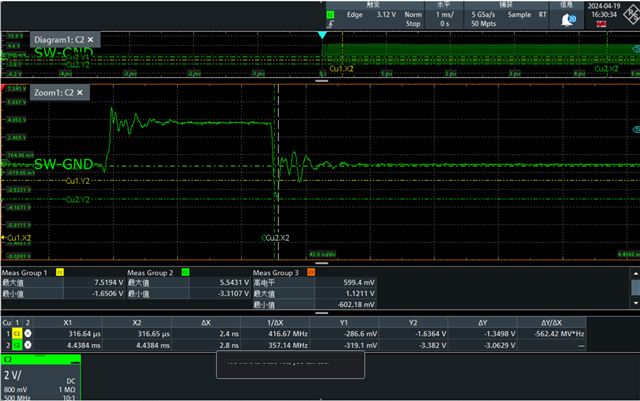
1. when output short to gnd, the VIN-SW voltage will be -1.6V@5ns;and the SW-GND voltage will be -3V@2.8ns.Dose this have some risks for our device? pls see the attached for details.

