This thread has been locked.

If you have a related question, please click the "Ask a related question" button in the top right corner. The newly created question will be automatically linked to this question.

TPS53681: outputoff

Part Number: TPS53681
Other Parts Discussed in Thread: CSD95490Q5MC

Tool/software:

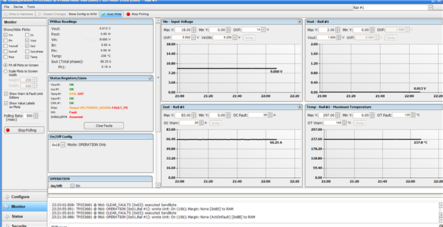
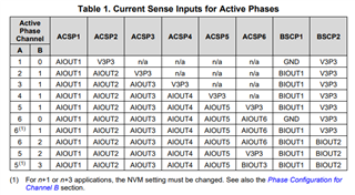
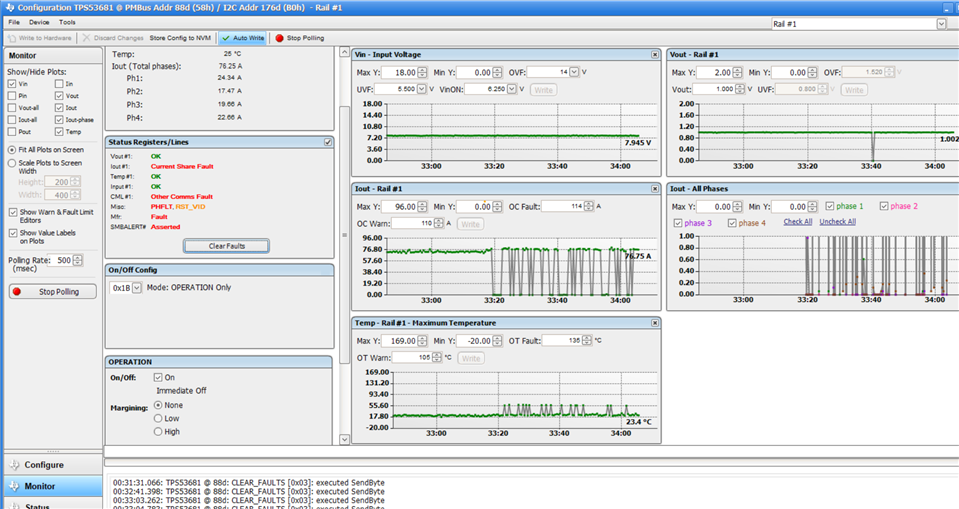
  • Dear staff, I encountered the following error while debugging a multiphase buck using TPS53681, which was designed by myself. It displayed a temperature error and no output voltage, displaying "output off", "fault_ps", and "power good" as shown in the figure. However, I used a temperature gun to display the temperature as normal, and I did not load during the debugging process, but the measured current was high. May I ask what is the reason? I only used the four channels of phase A, not channel B.MBUCK.pdf
  • Hi Jiaolong,

    'FAULT_PS' means that the powerstage is reporting a fault to the controller. Output will be off while the powerstages are reporting a fault to protect from any potential damage. Temperature being high and Iout being high are the lines that the powerstage uses to tell the controller it is faulted. This could be caused by many different reasons. 

    Using only the 4 channels of channel A is fine but you need to also set channel B to 0 phases or that may cause other issues as well. 

    Can you please share the datasheet for the powerstage you are using? I notice it is not a TI powerstage so there may be some difference with fault reporting. Can you please share your config as well?

    Best Regards,

    Nash 

  • Infineon-TDA21490-DataSheet-v02_00-EN.pdf

    This is the data manual for the intelligent power stage I am using. Regarding the configuration, I have shown in the schematic that I disabled the B channel (BVR_EN) by grounding pin 20 of the chip, and disabled the A channel 5 channel  by grounding pin 27. In the software, I only changed the output voltage without changing anything else. Can you tell me where else to set up? Thank you very much for your help!

  • Hi Jialong,

    Pin 27, ACSP5 should not be grounded and your schematic doesn't show it as grounded. Can you confirm if it is grounded or at 3V3?

    This chart shows the proper CSP configuration for various configurations. In your case, ACSP1,2,3,4 should all be connected to their respective powerstage and ACSP5 should be at 5V.

    If you have confirmed that the configuration is correct, then you may have an issue with the powerstages themselves. 

    Best Regards,

    Nash

  • Thank you for your reply. I apologize for providing incorrect information. I have connected ASCP5, ASCP6, and BSCP2 to 3.3V, and I have grounded BSCP1. I followed the design example and there should be no problem. May I ask if there are any other issues that caused the output to fail? I think my power stage connection is correct. The TDA21590 power stage chip I am using is roughly the same as the CSD95490Q5MC pin used in tps53681evm. I look forward to your reply

  • Hi Jialong,

    I believe you may have issues with the powerstages themselves. The fault being displayed with the controller is a fault from the powerstage. Unfortunately, I am unable to help you with the Infineon powerstages. 

    Best Regards,

    Nash

  • Thank you very much for your response. I re-soldered the chip and conducted a no-load experiment, where I found that all four phases could be detected and the output voltage was stable.

    However, one of the power stage chips had a significantly higher temperature than the others, so I replaced the intelligent power stage chip. Upon powering up and testing again, the software could only detect one phase of current.

    Where should I configure the settings? I couldn't find how to set it.

    I have Channel A configured for four phases, and Channel B is disabled. My ASCP5, ASCP6, and BSCP2 are connected to 3.3V, and BSCP1 is grounded. Could it be that the TPS53681 chip is damaged?"

  • Hi Jiaolong,

    If the board was functioning but one phase was higher temp, I would imagine that phase had either high side FET damage which was causing excessive powerloss or that the device had a soft short which caused excessive powerloss. I am not sure though how replacing one powerstage would cause 2 others to no longer function. There is always a chance that the controller was somehow damaged but that should be very unlikely. Since the powerstages had a soldering issue previously, it might be worthwhile to replace the controller.

    I am not sure what configuration settings you are asking about. 

    The configuration for Channel A and B should be ok.  

    Best Regards,

    Nash

  • Hello, during the power-on test with gradually increasing load current, the board experienced a fault and produced a vibrating noise, but it still maintained the current output.

    When I continued to increase the current,the board made a 'clicking' sound and the current fluctuation issue shown in the picture appeared.

    Using infrared thermometry, I found that one power stage was slightly dimmer compared to the others, but at lower output currents,the temperature appeared very balanced.

    What could be the possible reasons for this?

    Additionally, I did not connect the temperature output pins of the smart power stages to the temperature detection pins of the TPS53681, because when I connected them using 0-ohm resistors, errors always occurred."

  • Hi Jiaolong,

    It sounds like one of the powerstages may have been damaged in testing. The temperature output pins are also the fault reporting pins, so not connecting them will not allow the controller to turn them off when there is a fault. Having a fault before the powerstages are on means that there is more than likely a soldering issue that has caused a short of some sort.

    Please verfiy the voltage that you measure on each of the TAO pins on the powerstage.

    Best Regards,

    Nash