


Tool/software:
Hello,
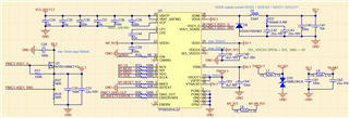
For our project, we decided to use the TPS65381A-Q1 PMIC for our design. I have several questions about the TPS65381A-Q1 schematic design. Schematics are attached.
The MCU used for this project is the TMS320F2800156. For the 1V2 core supply, the MCU has an internal LDO.
On the PMIC side:
The LDO capacitors (C59, C60) are CL21B475KOFNFNE.
The SMPS capacitors (C42, C43) are CL31B226KPHNNNE and use the same 100mOhm resistor.
The 33uH inductor (L6) is SRP1038A-330M.
To generate the 1.2V core supply from the PMIC to the MCU, Q1 is NTR5198NLT1G.
My questions are as follows:
1-Is the schematic correct?
2-Can we use the VDD1_SENSE pin to monitor the MCU's internal LDO for the 1V2 core supply (without generating 1V2 from the PMIC side)?
3-Is the R31 value suitable for our application (according to the effective capacitance of C42 and C43)?
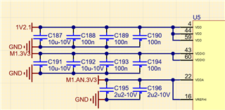
4-According to the datasheet, effective capacitances should be a maximum of 5uF for the 5V and 3V3 LDOs. Do the other capacitors on the same label cause any trouble in the design (e.g., M1.3V3 label LDO side C59 and MCU side C191 and C192)?
5-Is there any application note for using C2000 MCUs and the TPS65381A-Q1 PMIC?
Edit: For question 2 I have seen a post https://e2e.ti.com/support/power-management-group/power-management/f/power-management-forum/747190/faq-tps65381a-q1-can-the-vdd1_sense-pin-be-used-to-monitor-another-regulator-output-if-vdd1-ldo-controller-isn-t-used-in-the-application
We want to monitor exactly 1V2. For reference sheets, resistor values are set to sense 1V23 output with R27->43.2R and R29->80.6R. Can we use 40R and 80R for R27 and R29?
Best regards.
