This thread has been locked.

If you have a related question, please click the "Ask a related question" button in the top right corner. The newly created question will be automatically linked to this question.

TPSF12C3-Q1: Is TPSf12C3-Q1 possible to use 3 phase square wave of several hundred V and several hundred Arms?

Part Number: TPSF12C3-Q1
Other Parts Discussed in Thread: TPSF12C3

Tool/software:

Dear Specialists,

My customer is interested in TPSF12C3-Q1 and  has a question.

I would be grateful if you could advise.

---

(1) Is TPSF12C3 possible to use for high voltage, high current applications as long as the common mode voltage (SENSE1, SENSE2, SENSE3, SENSE4 to REFGND) is within ±5V?

(For example, three-phase square waves of 0V to several hundred V, several hundred Arms)

(2) I think the TPSF12C3 is a voltage detection, current compensation type VSCI.

Does the current actually measure in the detection part of the circuit?

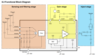
Are the resistors between Sensex and REFGND in the sensing and filtering stage( in the detection part of the datasheet p9 8.2 Functional Block Diagram) a shunt resistor?

ーーー

I appreciate your great help in advance.

Best regards,

Shinichi

  • Hi Shinichi,

    1.  Yes, it is possible to use TPSF12C3 for high voltage, high current applications as long as the common mode voltage (SENSE1, SENSE2, SENSE3, SENSE4 to REFGND) is within ±5V. You can refer to the datasheet absolute maximum ratings table for more details. 

    2. Yes, it is a voltage sense current inject architecture. The resistors between Sensex and REFGND in the sensing and filtering stage are shunt resistors. But they are not accessible as they are within the IC. 

    Thanks and Regards,

    Naresh. 

  • Hi Naresh,

    Thank you for your reply.

    I understand.

    I'll share the information with the customer.

    When the customer has an additional question, I consult you again.

    I appreciate your great help and cooperation.

    Best regards,

    Shinichi

  • Sure Shinichi. You can go ahead and share the information with the customer. 

  • Hi Naresh,

    I sent your answer to the customer, the customer has additional questions.

    Could you please advise?

    ---

    (1)You mentioned that the resistor between SENSEX and REFGND is a shunt resistor.

    I understand that in the Σ block after the voltage is converted by the shunt resistor, the current value between GND and each SENSE is added as a voltage, and the added current value is returned to the three phases. Does my understanding correct? 

    (2)I think that when CY1, CY2, and CY3 in the Passive filter circuit in Figure 8-1 on page 10 of the TPSF12C3 data sheet are not connected to earth, the potential changes stepwise in the range of the input DC voltage of the 3-phase AC supply. (For example, if DC600V is input, it changes in steps of 200V in the range of ±300V.)

    CSEN3, CSEN2, and CSEN1 in the Active filter circuit are also connected to earth in the IC, so is it correct to assume that there is almost no potential fluctuation (within ±5V)?

    (3)According to the datasheet P6., the INJ current at linearity limits is ±80mA. When a CM current of more than ±80mA, can we assume that the noise reduction effect will decrease?

    (4) Also, if you have any detailed materials on the detection voltage and compensation current, please send them to me.

    ---

    I appreciate your great help and cooperation.

    Best regards,

    Shinichi

  • Hi Naresh,

    This is a reminder I'm looking forward to waiting your answer about additional questions.

    I appreciate your great help and cooperation.

    Best regards,

    Shinichi

  • Hi Shinichi,

    I will get back to you.

    Thanks and Regards

  • Hi Shinichi,

    1. The sense capacitor along with the shunt resistor acts as a high pass filter and then it goes through the Σ block and then to the Filter stage. 

    2. Yes, CSEN3, CSEN2, and CSEN1 in the Active filter circuit are connected to earth in the IC, so it is safe to assume that there is almost no potential fluctuation (within ±5V). 

    3. Yes that's true, as the INJ current at linearity limits is ±80mA. When a CM current of more than ±80mA, the noise reduction effect will decrease.

    4. could you please also refer to white paper in the product link (TPSF12C3 data sheet, product information and support | TI.com). It has more information 

    Thanks and Regards,

  • Hi Naresh,

    Thank you for your reply.

    I'll share the answer  with the customer.

    I appreciate your great help and cooperation.

    Best regards,

    Shinichi