This thread has been locked.

If you have a related question, please click the "Ask a related question" button in the top right corner. The newly created question will be automatically linked to this question.

UCC28782: Burst mode operation

Part Number: UCC28782

Tool/software:

Hello,

I would like to ask you a question regarding the burst mode operation of the UCC28782.
(Question 1)
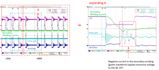
When transitioning from LPM to ABM, excessive voltage is applied to the SR_FET Vds.
Please see the enlarged waveform in the figure below.
When transitioning from LPM to ABM, the first wave of PWMH (Hiside_gate) seems to be extended beyond normal operation so as not to put stress on the SR_FET, according to 8.1 Overview in the datasheet.
However, in the operation shown in the figure below, it is not extended, which seems to be the cause of excessive voltage being applied to the SR_FET.
Is the operation shown in the waveform below expected?

(Question 2)
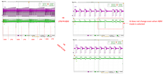
Even though I have set a hysteresis of 100mV or more for ΔBUR (LPM), LPM mode and ABM mode are repeatedly occurring.
I tried increasing the hysteresis of the BUR pin, but there is no improvement.
Is there any reason for this behavior?
When transitioning from LPM to ABM, the Vcst (BUR) threshold rises, so Id (peak current of the low-side FET) for the first wave when ABM starts should also rise, but it has not. It has not risen from the second wave onwards either.
Is this symptom normal?

Best regards,

  • Hi Kaji-San,

    Thank you for reaching out.

    The high voltage on SR FET could be due to following:

    The 1st PWMH on time was determined by RDM pin resistor & Vout sense (through VS pin) & Primary peak current (Vcst decided by FB loop). what you can change or revise is the RDM pin resistor . Decrease RDM resistor will short  1st  PWMH on time .

    Once 1st PWMH on time is shortened by decreasing RDM resistor,  the clamp capacitor will not be over discharged(voltage drop) . if the secondary reflected voltage >= clamp capacitor voltage in next PWMH on time , there is no reverse current from secondary to primary to charge the Cclamp. So the spike can be reduced.

    And if you use a SR controller which has short minimum on time also will help for reducing the reverse current.

    Also this is normal, please refer page-15

    https://www.ti.com/lit/an/slua982/slua982.pdf?ts=1717497197147&ref_url=https%253A%252F%252Fwww.ti.com%252Fproduct%252FUCC28780

    The gain between VBUR and VCST(BUR) is a constant gain of KBUR-CST, so setting VCST(BUR) just requires properly selecting the resistor divider on the BUR pin formed by RBUR1 and RBUR2. VBUR should be set between 0.7 V and 2.4 V. If VBUR is less than 0.7 V, VCST(BUR) holds at 0.7 V / KBUR-CST. If VBUR is higher than 2.4 V, VCST(BUR) stays at 2.4 V / KBUR-CST. So Vbur needs to be checked.

    Regards,

    Harish