Tool/software:
We are using a battery charger from TI (BQ25180YBGR) in a project. I have now carried out the design check of our board and I have noticed something in the voltage curve of the battery charger that I cannot explain.
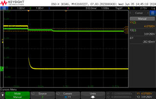
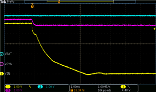
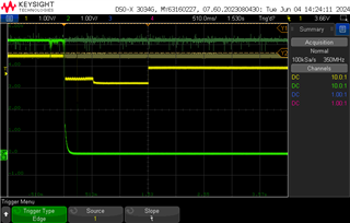
I have attached a picture of my oscilloscope measurement. CH1/green is the V_USB which corresponds to the USB voltage and CH2/yellow is the V_SYS which is the output from the Battery Charger. In this example, a battery is also connected to the battery charger and V_SYS is then regulated to 3.3V by the board. During the measurement, I unplugged the USB cable to analyse how the switching behaves. At the beginning, V_SYS is approx. 4.2V, which corresponds to the specifications in the data sheet. However, as soon as I disconnect the V_USB, the voltage drops to approx. 3.3V for 1.5 seconds, then goes to the voltage corresponding to the V_BAT, which is correct so far. However, I cannot explain the drop, and it is possible that it makes the system very sensitive during switching.
Can anybody explain this switching, or rather this voltage drop?